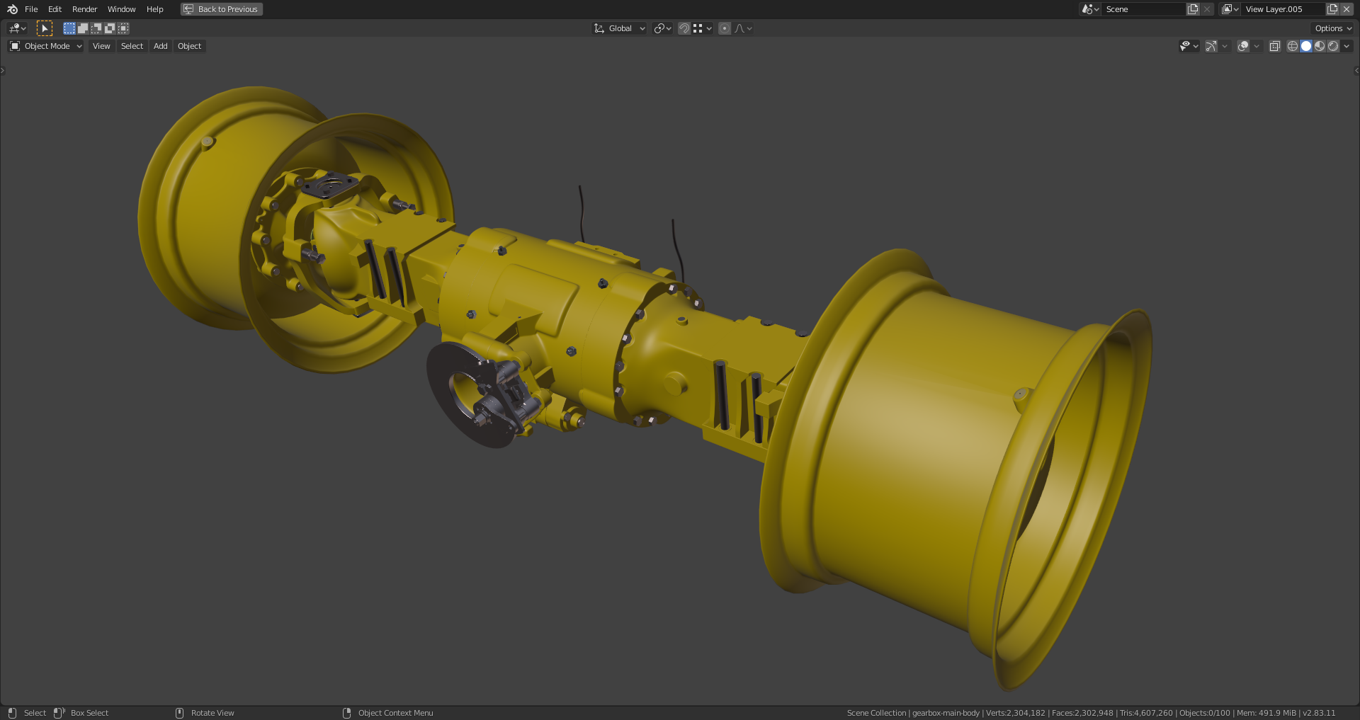
This thread is dedicated to the wheels and the rear axle of the backhoe project.
Didn't notice this before, but there is some pinching here: 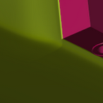
might be easy to solve, by merging those three close-together edge loops at the bottom. 
Something like this: 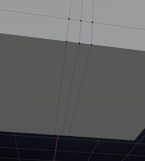
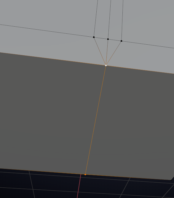
and:
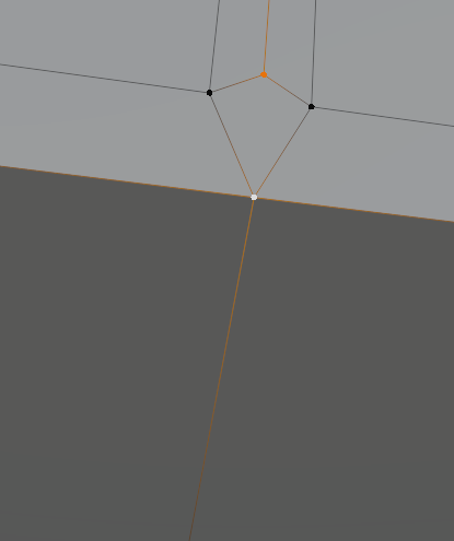
Might not work in your case, but it's worth a try.
Don't stress out too much if you can't solve it, with the right shader (dirty, greasy, damaged, painted iron) you'll be able to hide it;)
Now, the gearbox side rings and the green-blue part are all quads and without any 6-poles:
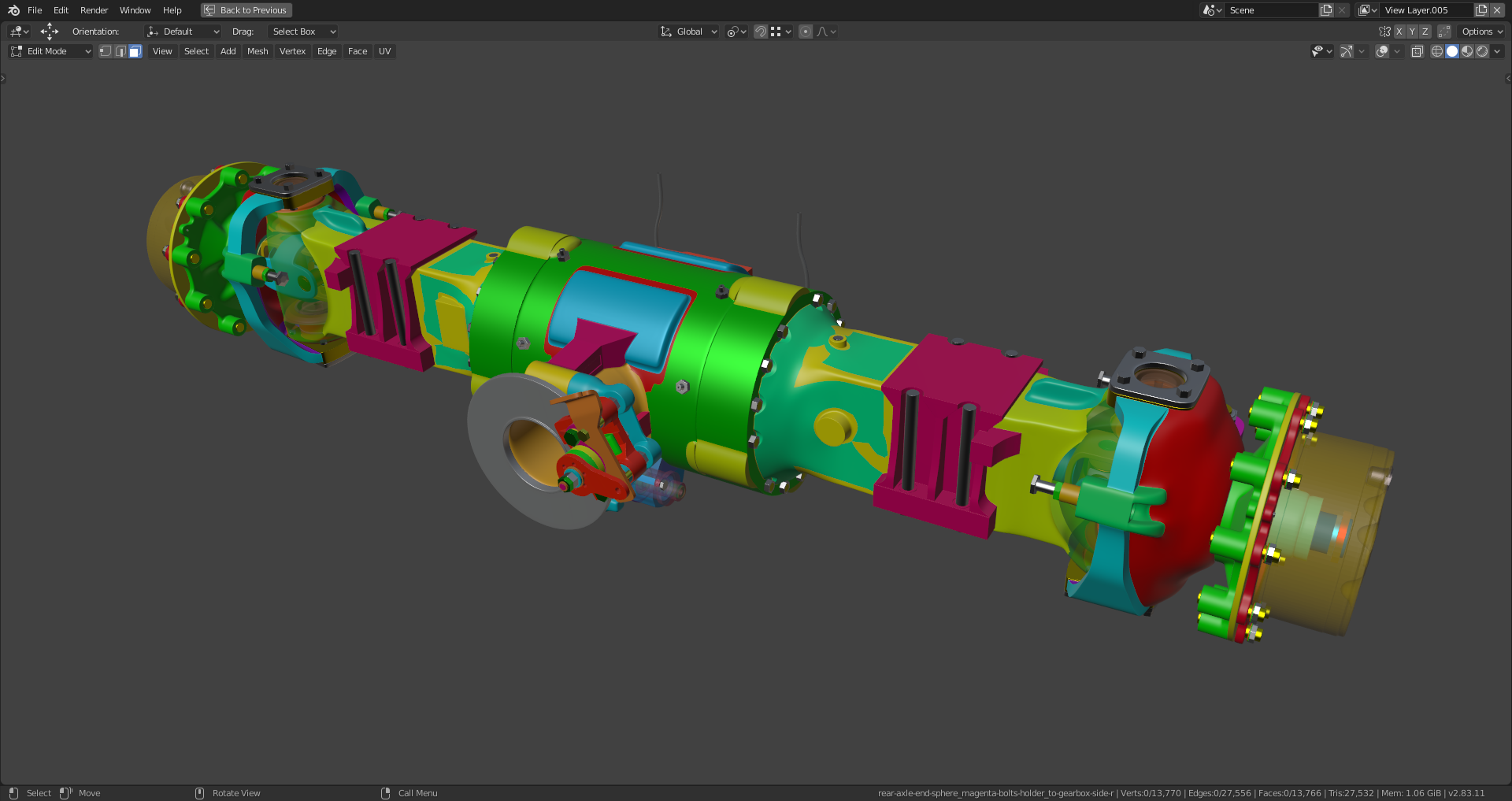
The green-blue element to the right of the gearbox is a mirrored in global Y duplicate of its axle left side counterpart.
Hey Ingmar ![]() duerer that is looking just amazing.
duerer that is looking just amazing.
One thing I noticed that probably should be addressed at some point is that your assembly when linked is shown all over the place.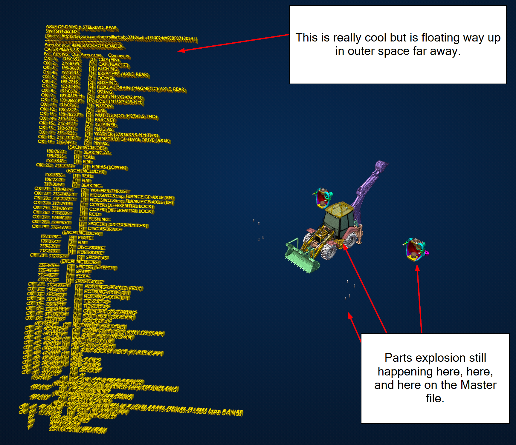
I'm currently cleaning up my file removing all parentships. This should solve the issue.
The hub and the first attachment ring are now one continuous part as on the real backhoe:
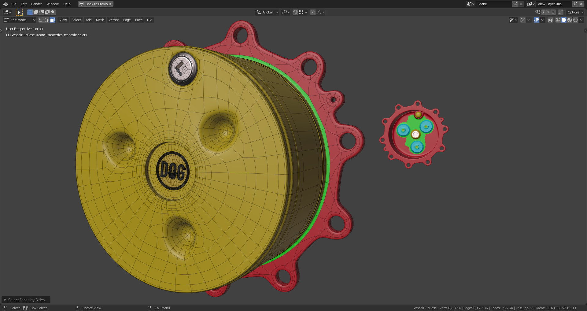
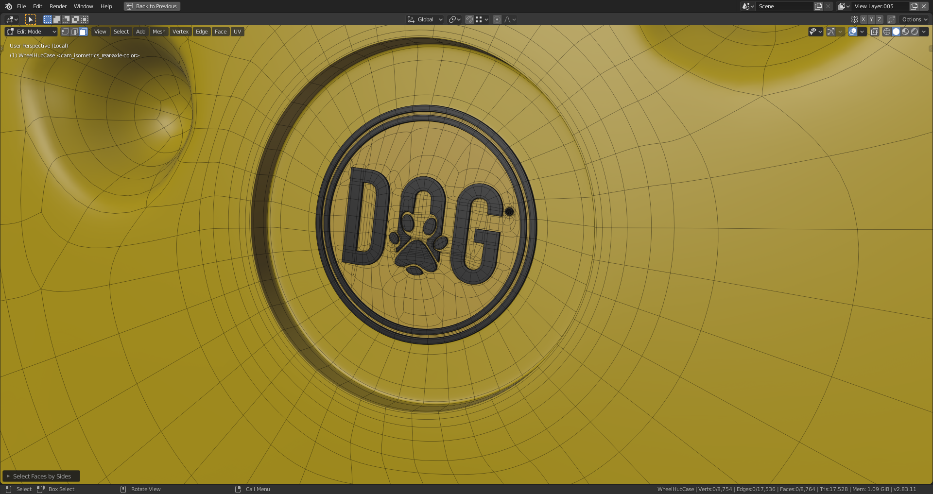
The "Dog" logo is also now connected with the hub in a retopologized version:
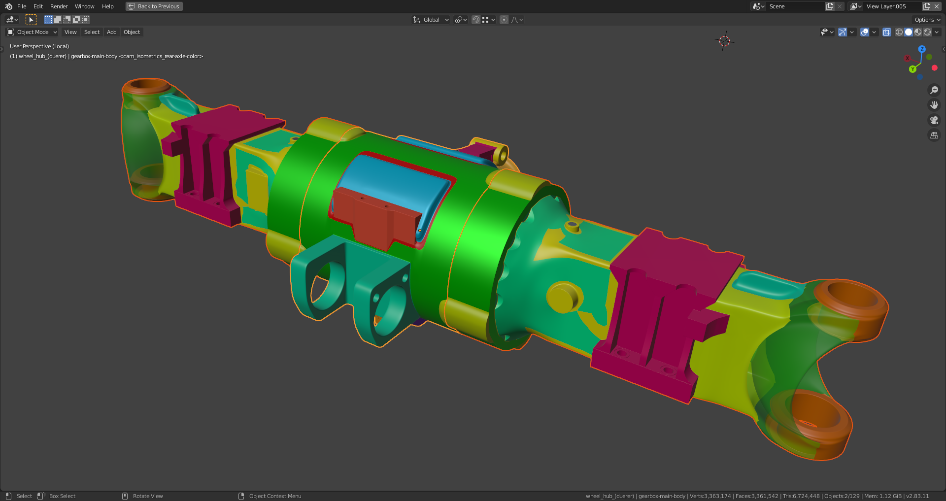
The "Shrinkwrap Modifiers" on the gearbox can only be applied after applying the preceding "Subsurf Modifiers" (Level 2) in order to get the correct shape:
Looks like you're really close to finishing, amazing job!
Only thing is, some edges are really sharp like here:
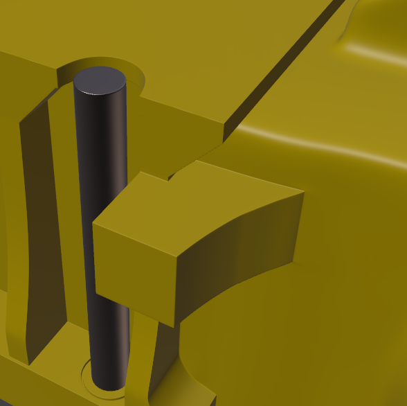
Those holding edges are too close I think:
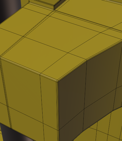
If you just slide them away from the edges:
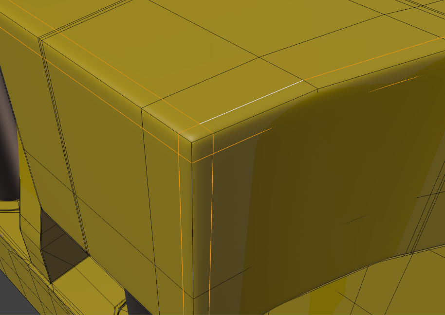
It will look better and more consistent to the rest:
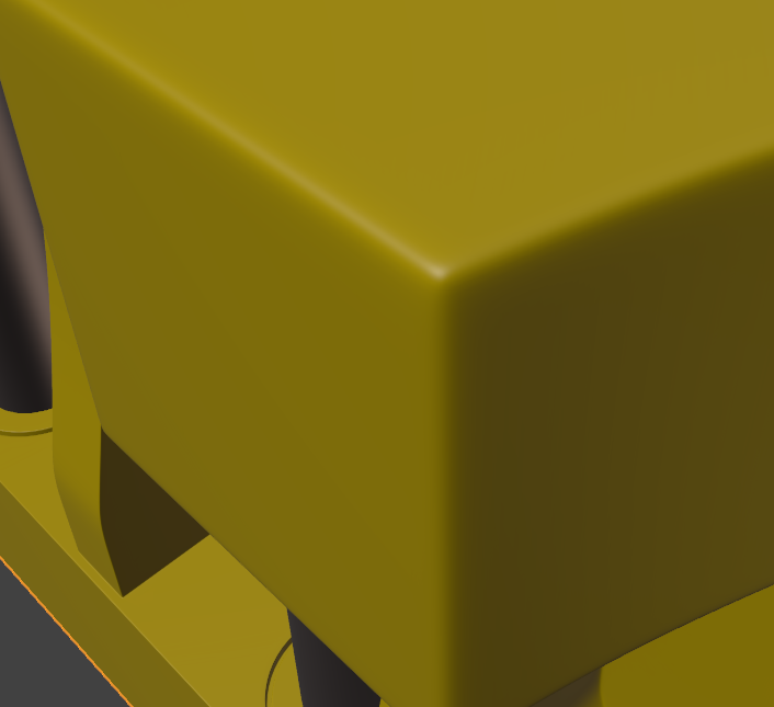
Maybe round it out even a bit more, when looking at reference:
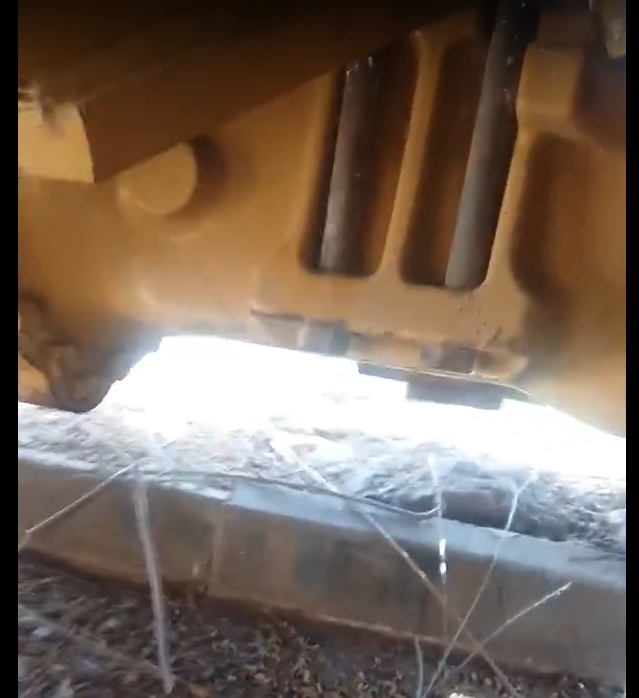
Anyway: great job on such a complicated part!
You're absolutely right, ![]() spikeyxxx, with the too sharp edges. This is bothering me, too. But it's relatively easy to fix. It's a remnant from the time when I used the "Bevel Modifier" with activated bevel clamping which was triggered very early by areas with extreme dense geometry. The main thing for me is that the rear axle fits into the chassis and the connections to the front are correct. With everything in place, the edges can be softened without causing any problems on the transitions from the rear axle to the adjacent parts.
spikeyxxx, with the too sharp edges. This is bothering me, too. But it's relatively easy to fix. It's a remnant from the time when I used the "Bevel Modifier" with activated bevel clamping which was triggered very early by areas with extreme dense geometry. The main thing for me is that the rear axle fits into the chassis and the connections to the front are correct. With everything in place, the edges can be softened without causing any problems on the transitions from the rear axle to the adjacent parts.
I could be mistaken, but I think that the ones you have are meant for situations like this:
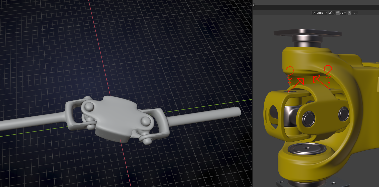
where the two axes are aligned, but offset from one another...
whereas a 'single' universal joint would be used to 'go around a corner'
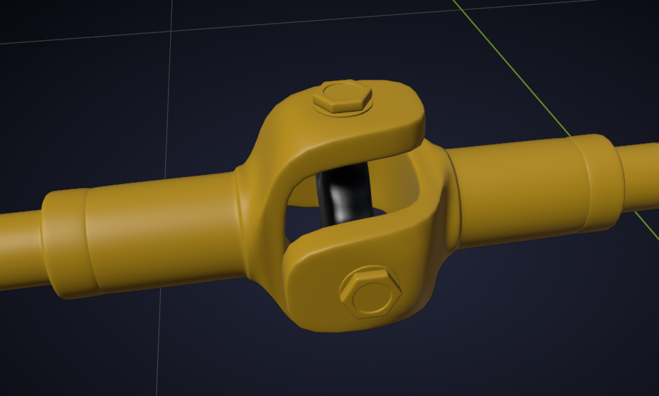
Then, also, the alignment wouldn't be a problem...
So this is my rear axle for assignment 5:
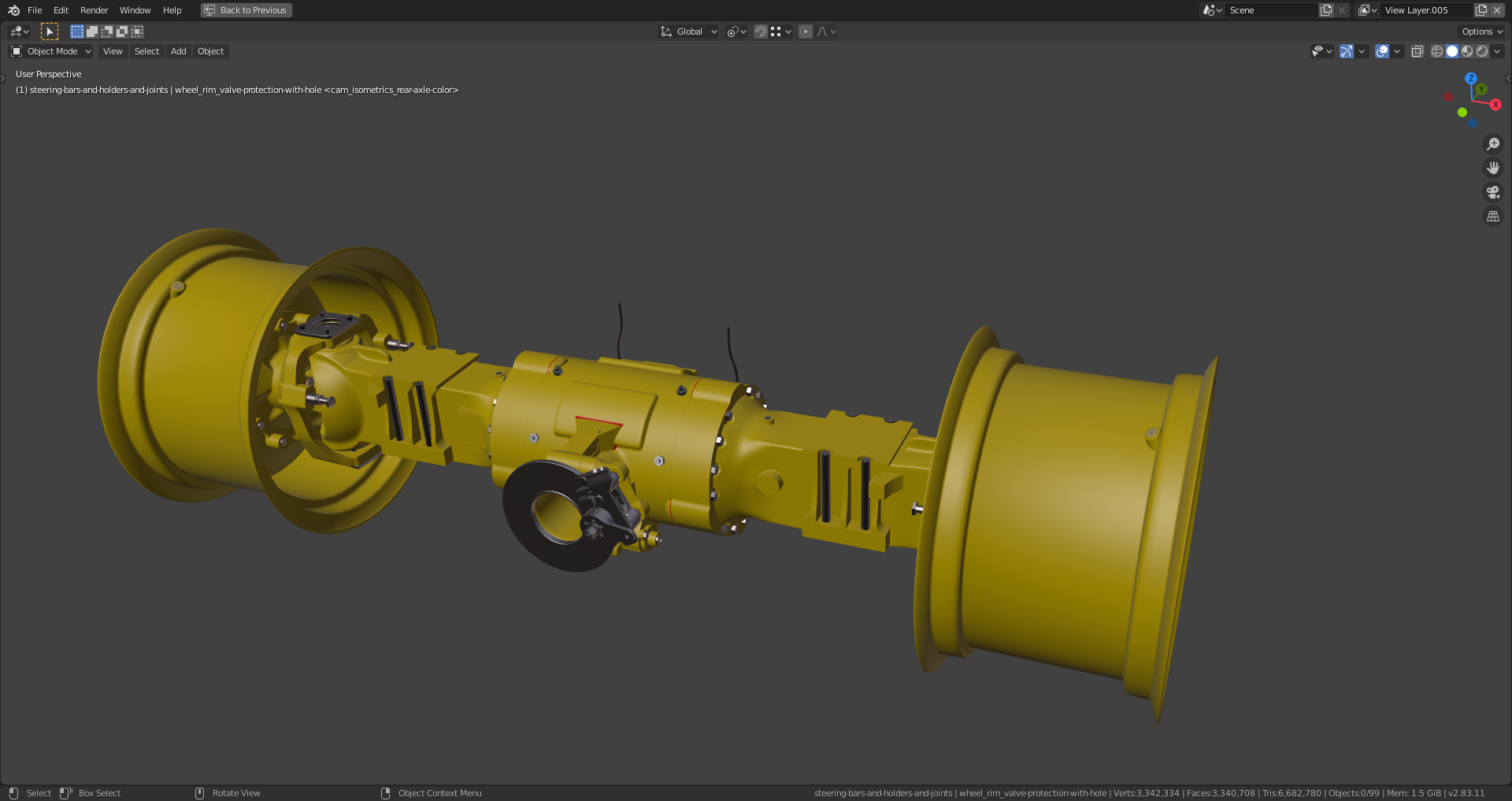
This is what I could do so far. I need some help for solving the shrinkwrap problems on the gearbox (marked in red) and the alignment of the yokes mentioned in the previous post.
File is here.
And this yoke is currently floating in the air together with the bars at both sides 🤔.
A very confusing drawing, but it seems to me that that 'yoke' part in the drawings is positioned more to the middle and that the ones that connect directly to the wheels are not even drawn here. In the top drawing there are these lines to indicate where the parts go and part 3 comes about where part 5 is...That position seems to be confirmed in the bottom drawing. (At least that is how I read it...)
The double yokes are on both axles in the axle and housings:
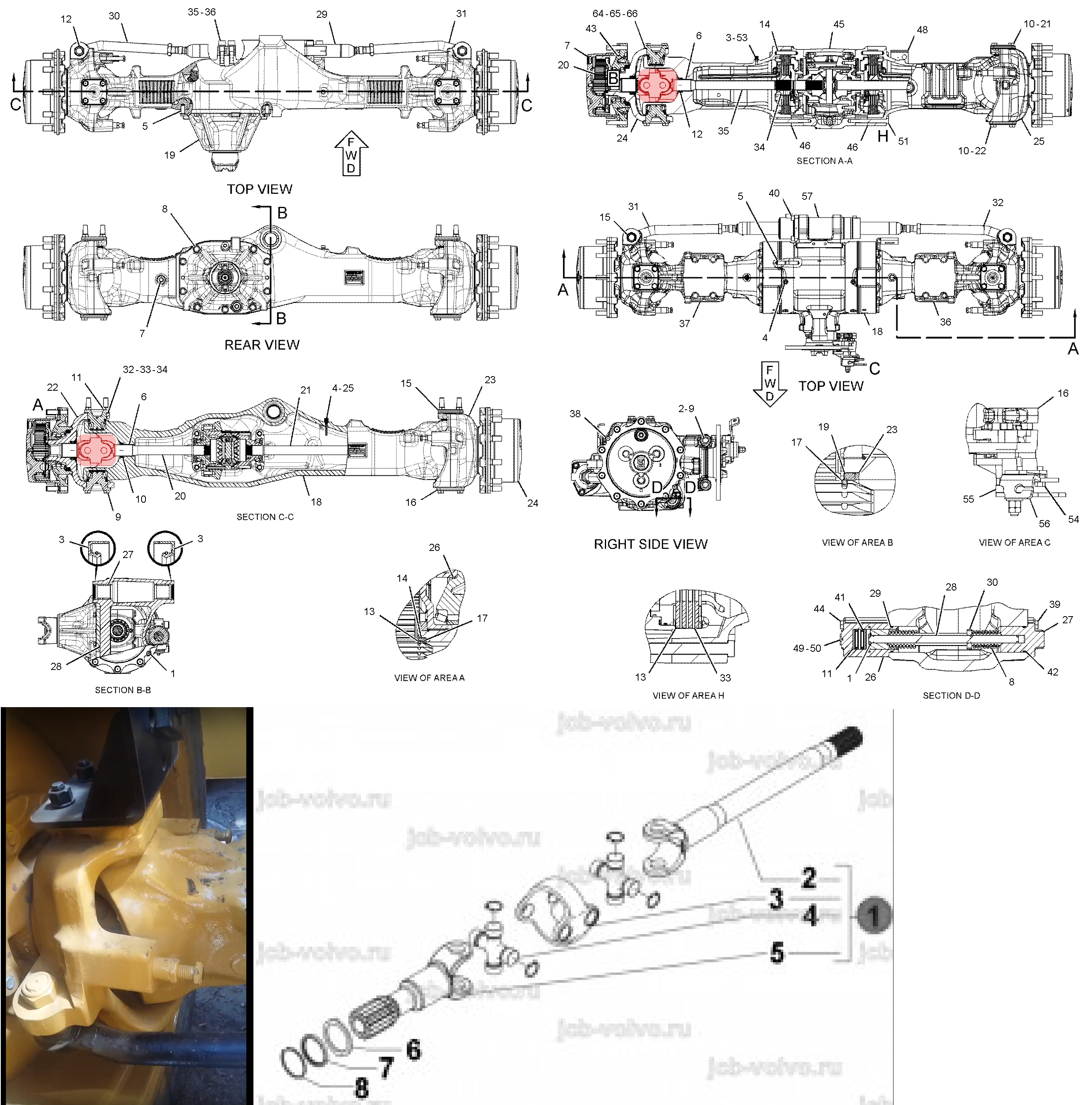
So, my alignment is already correct, but I still can't imagine how the bar connecting the yoke to the gears in the gearbox can transform its rotation around around the own length axis into two rotations perpendicular to that within the yoke structure.