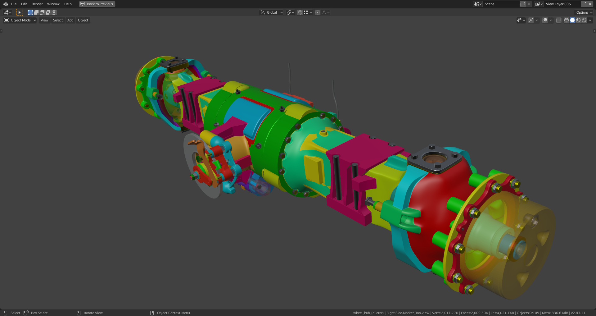
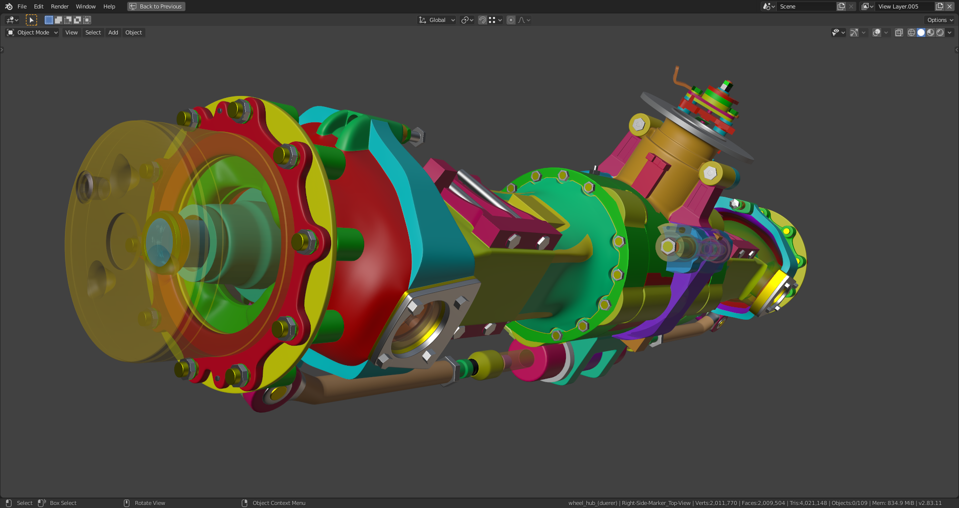
This thread is dedicated to the wheels and the rear axle of the backhoe project.
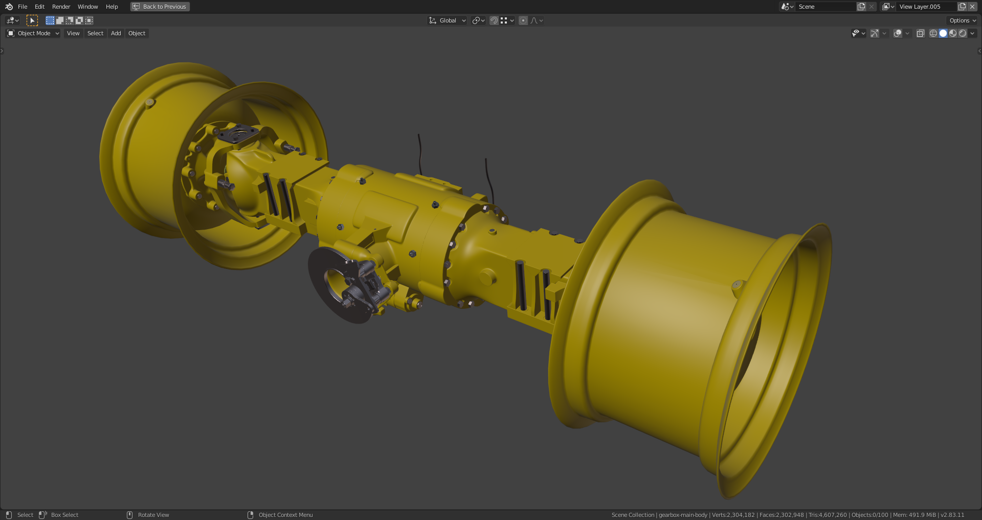
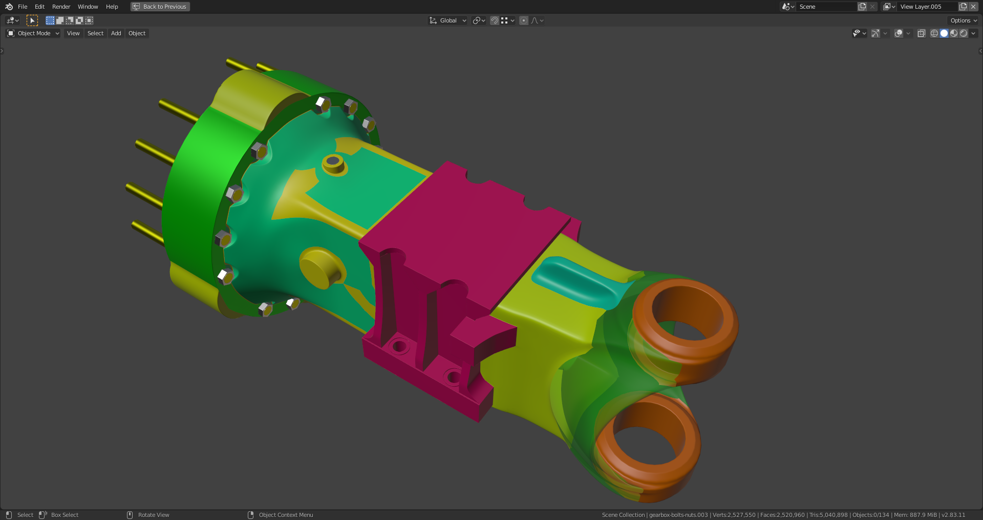
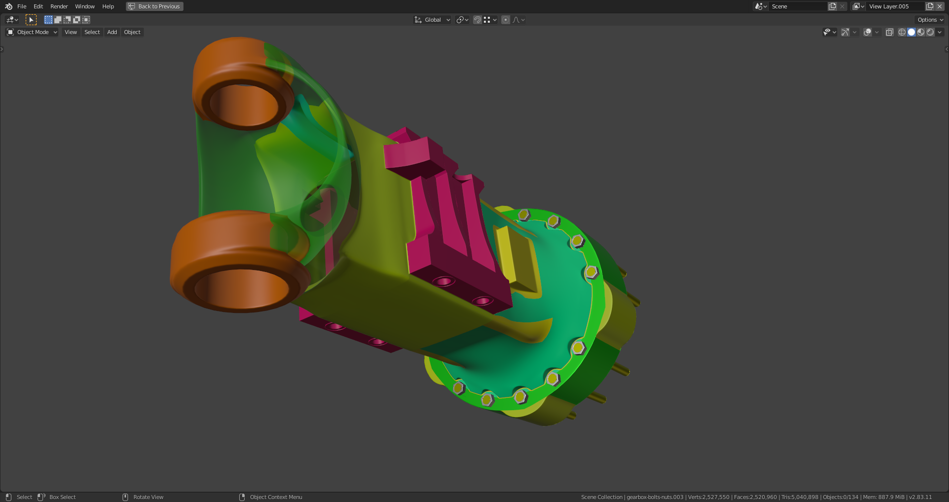
Two new parts (highlighted in the image below) connected but they need further tweaking:
Yes, @theluthier and ![]() blanchsb , that's exactly what came to my mind when I saw
blanchsb , that's exactly what came to my mind when I saw ![]() spikeyxxx's very detailed review 👍. I was really fascinated how you, @spikeyxxx , spot even the slightest discrepancy and explain it right on the point what's wrong together with a clear proposal on how to solve the problem. Thank you,
spikeyxxx's very detailed review 👍. I was really fascinated how you, @spikeyxxx , spot even the slightest discrepancy and explain it right on the point what's wrong together with a clear proposal on how to solve the problem. Thank you, ![]() spikeyxxx ,
spikeyxxx , ![]() blanchsb and @theluthier for the feedback and the encouragement 😀 !
blanchsb and @theluthier for the feedback and the encouragement 😀 !
The bottom part of the gearbox needed some reshaping. This is the still unfinished status so far:
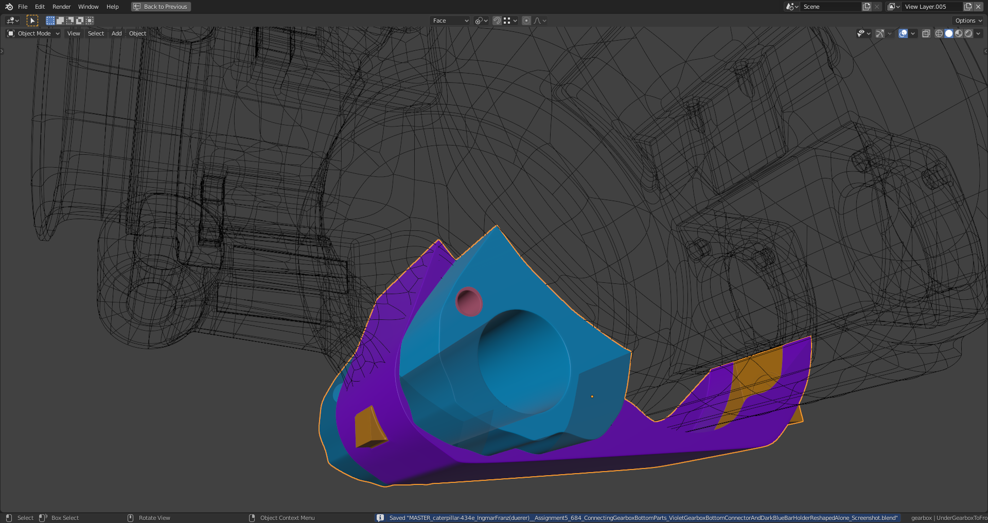
File is here.
The gearbox is now one connected mesh, but not yet all quads. Nevertheless, the "Shrinkwrap Modifier" does a good job:

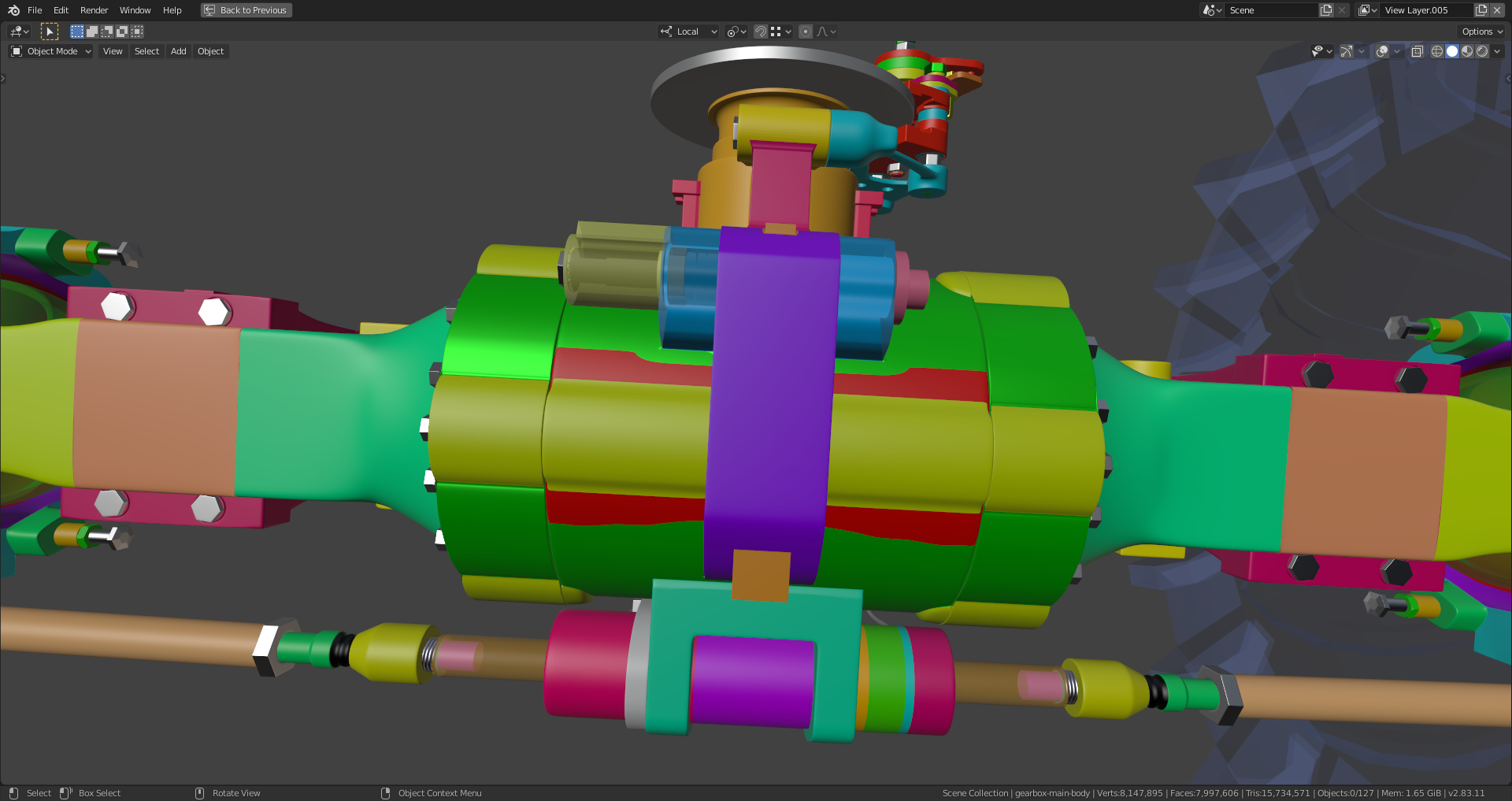
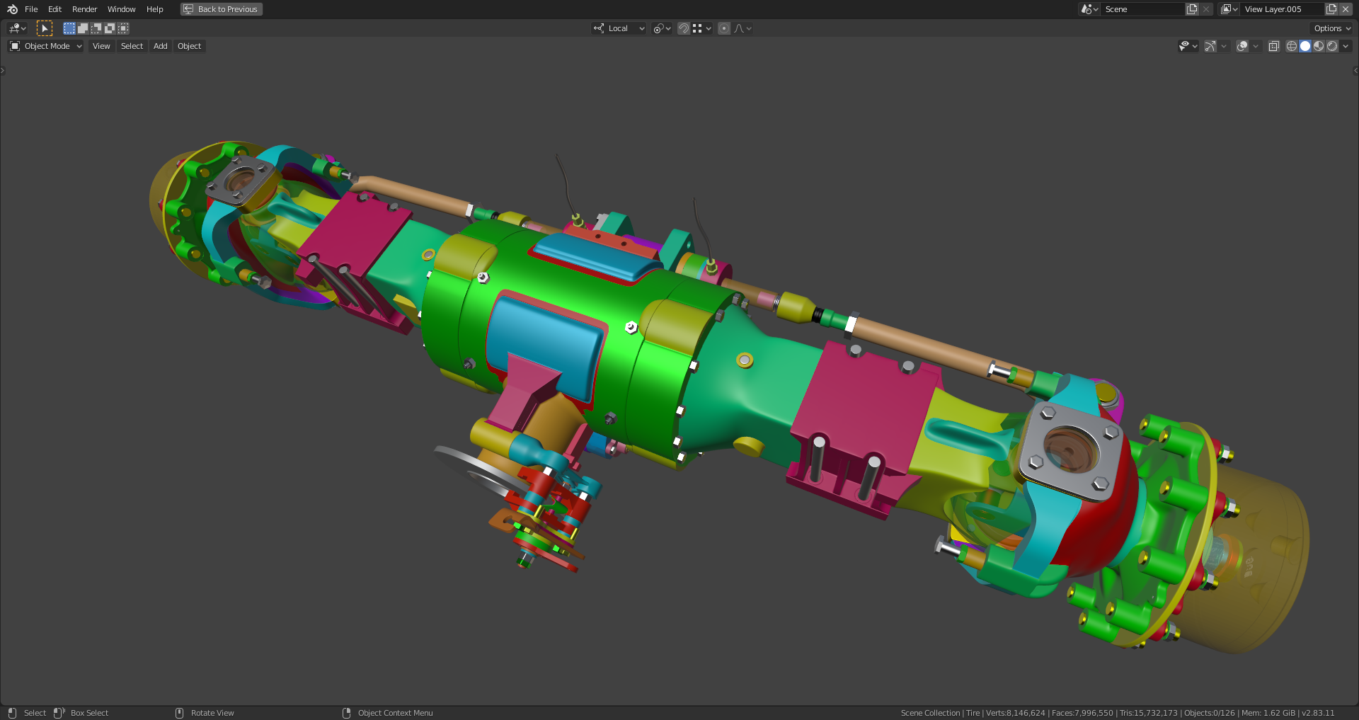
This is now also one mesh:
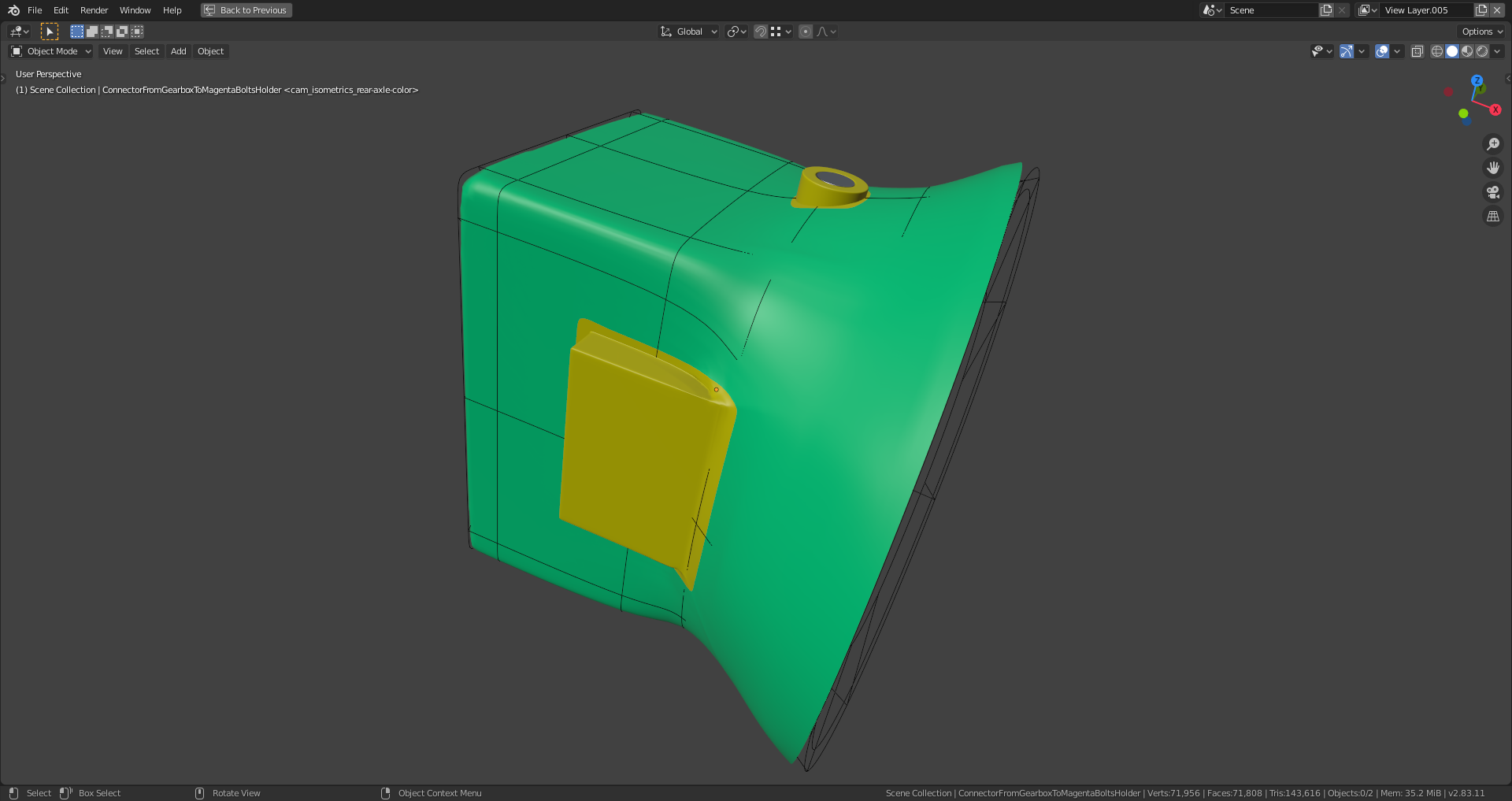
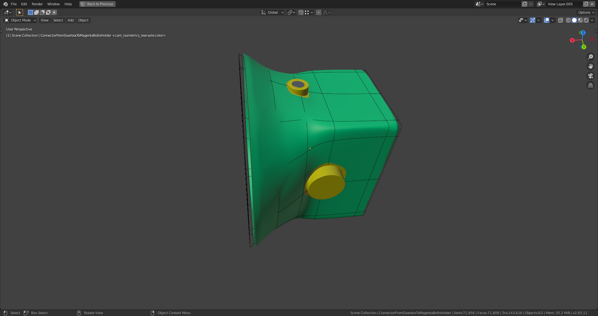
The wireframe is from the skrinkwrap target which is just a copy of the old separate main body. I worked with vertex weights and different projection methods ("Nearest surface point" and "Project" along local axes). Maybe some smoothing will be necessary after applying the modifiers. File is here.
There is a 'strange' quad here:
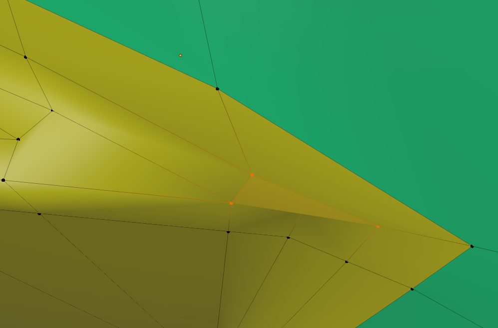
and a 5-sided pole directly at the 'transition area/point'.
I played around a bit and came up with something like this:
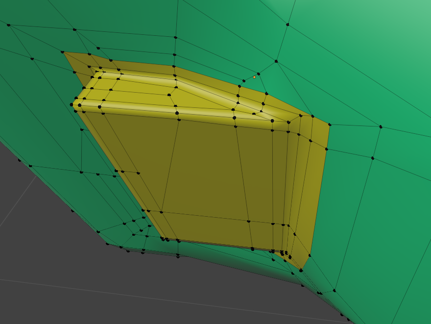
Got rid of the first Shrinkwrap and reduced the Subsurf to 2 levels and then it looks like this:
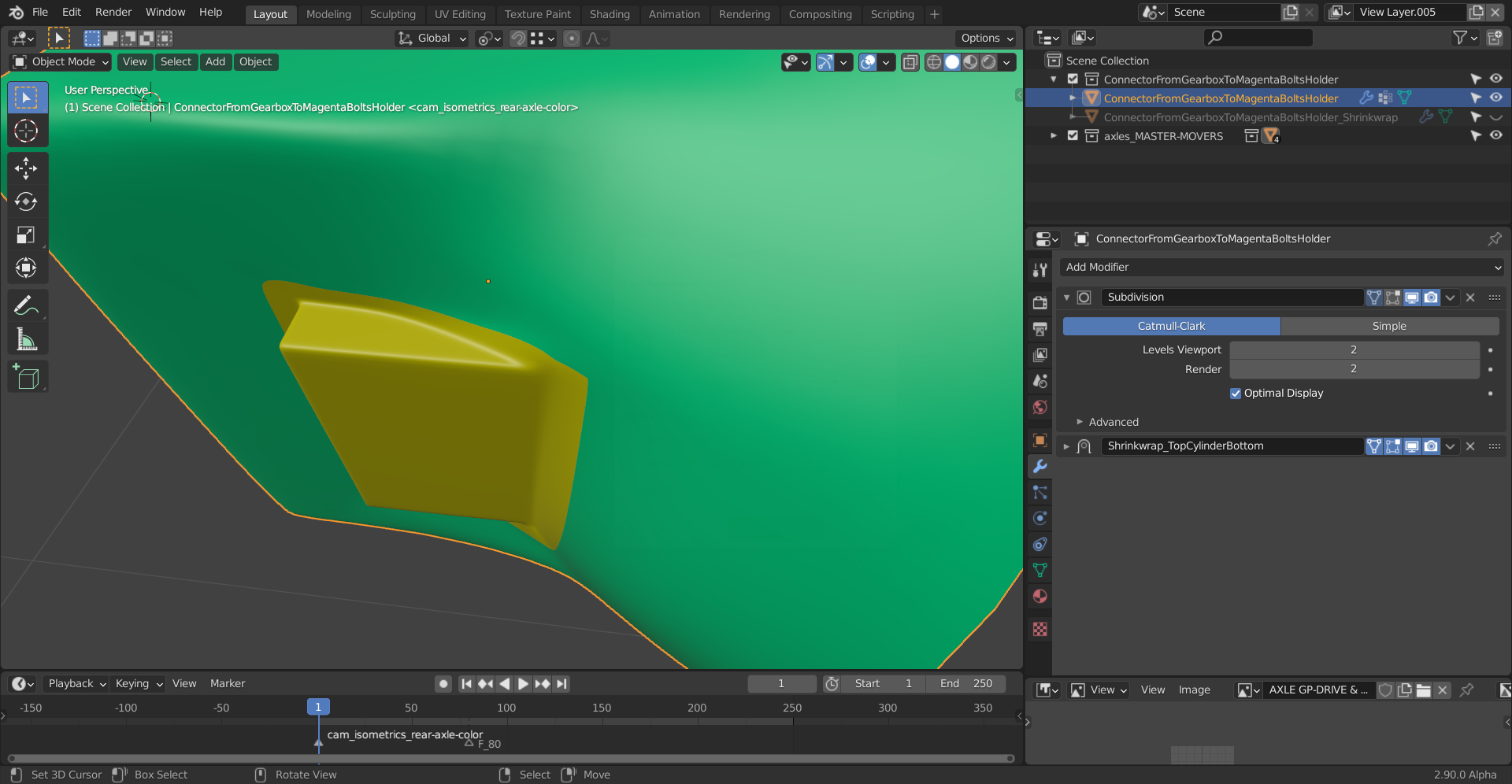
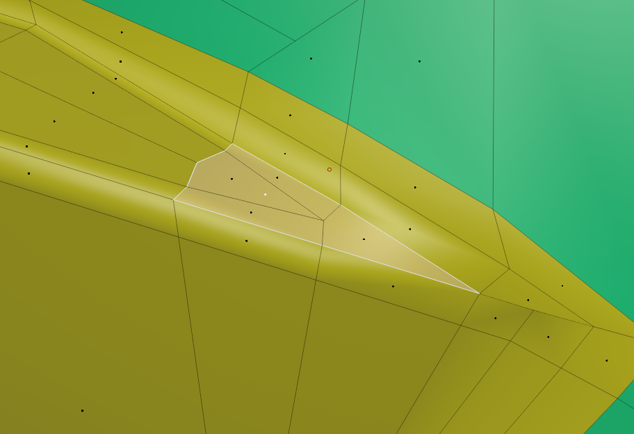
But your biggest problem is this extra Face that shouldn't be there:
Thank you, @spikeyxxx, this looks much smoother than before! The first "Shrinkwrap Modifier" was just for keeping the original shape as much as possible. Don't I come too much off from that shape if I delete that modifier?
You will deviate from that original shape a bit, but see how you like it. Remember that these are cast iron shapes, with maybe some of the shapes welded on. That is a different look than the thin, pressed metal plates that form the outside of a car. And Shrinkwrap might ruin that effect.
Also using the Shrinkwrap Modifier with Vertex Groups or even Vertex Weights is very dangerous. I used it on my ' Bee-hicle' project, but it was a frustrating experience of applying the Shrinkwrap and re-adding one, several times. Don't get me wrong: it can be done, but like all magic: it comes with a cost...
You're absolutely right, ![]() spikeyxxx , with being very carefull with vertex weights. I'm currently experimenting a lot in order to avoid any steps due to shrinkwrapping or, if I can't (easily) avoid them, bring me at least into a good position for final polishing after having applied the modifiers.
spikeyxxx , with being very carefull with vertex weights. I'm currently experimenting a lot in order to avoid any steps due to shrinkwrapping or, if I can't (easily) avoid them, bring me at least into a good position for final polishing after having applied the modifiers.
The gearbox consists now only of quads, but the shrinkwrapping still needs some tweaking, especially at the yellow pads on both sides of the gearbox:
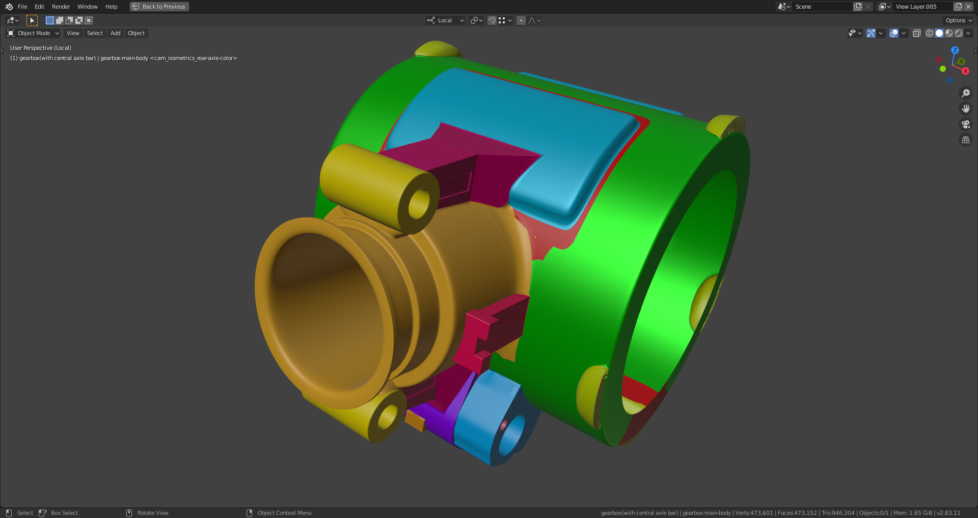
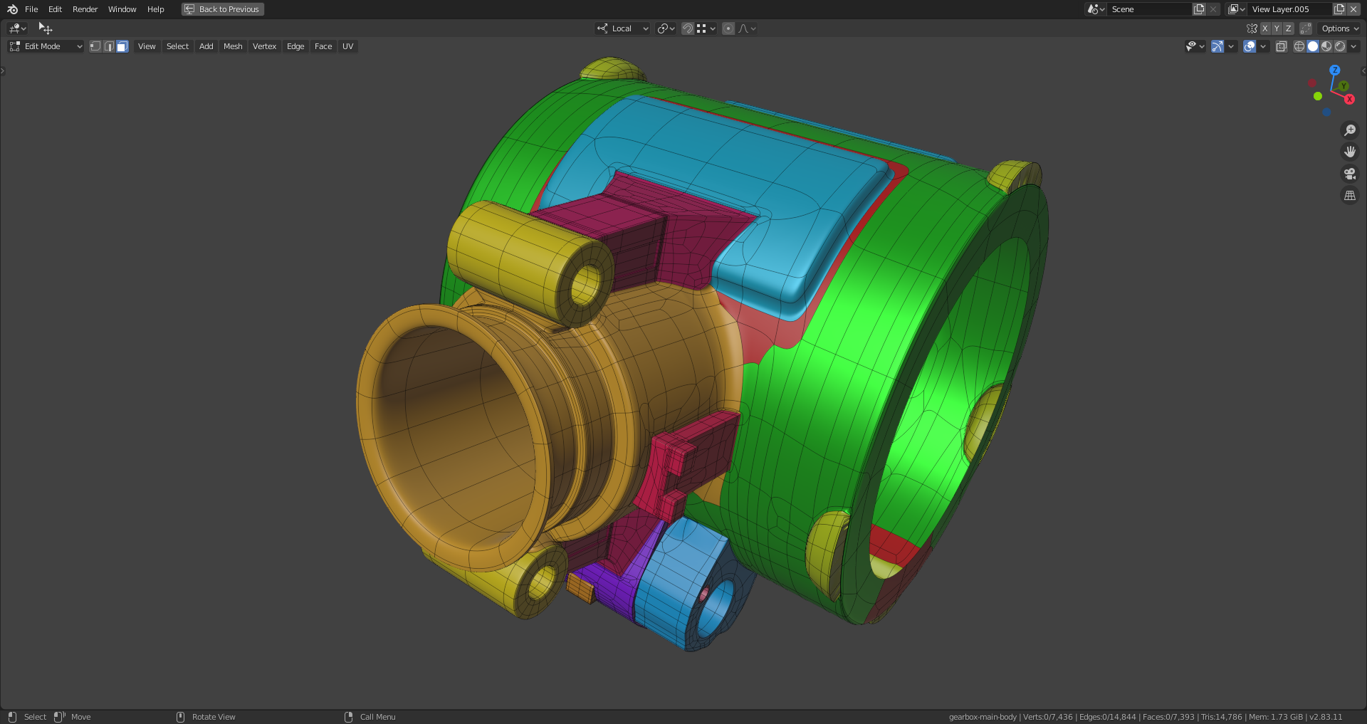
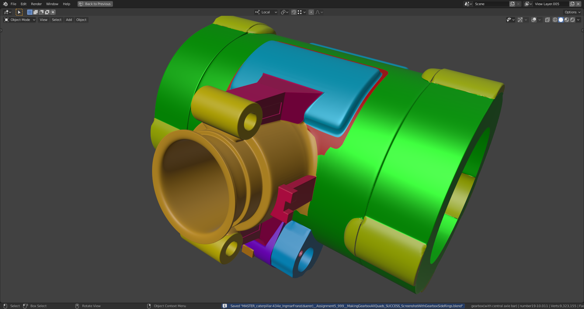
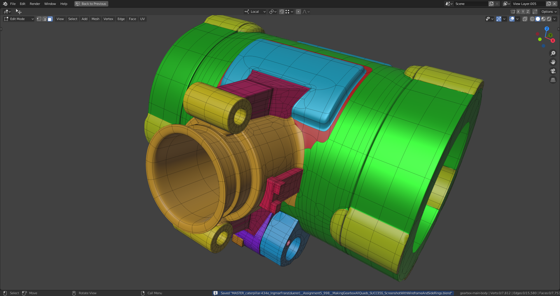
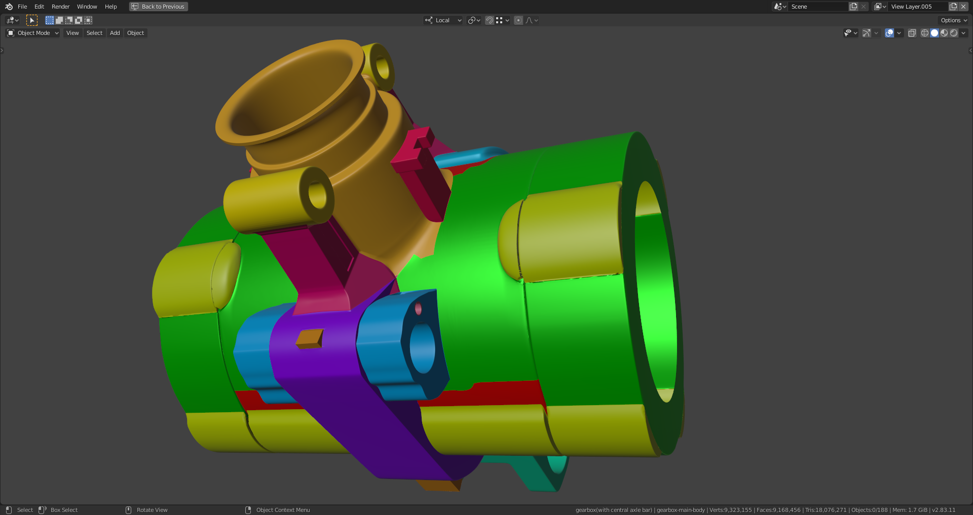
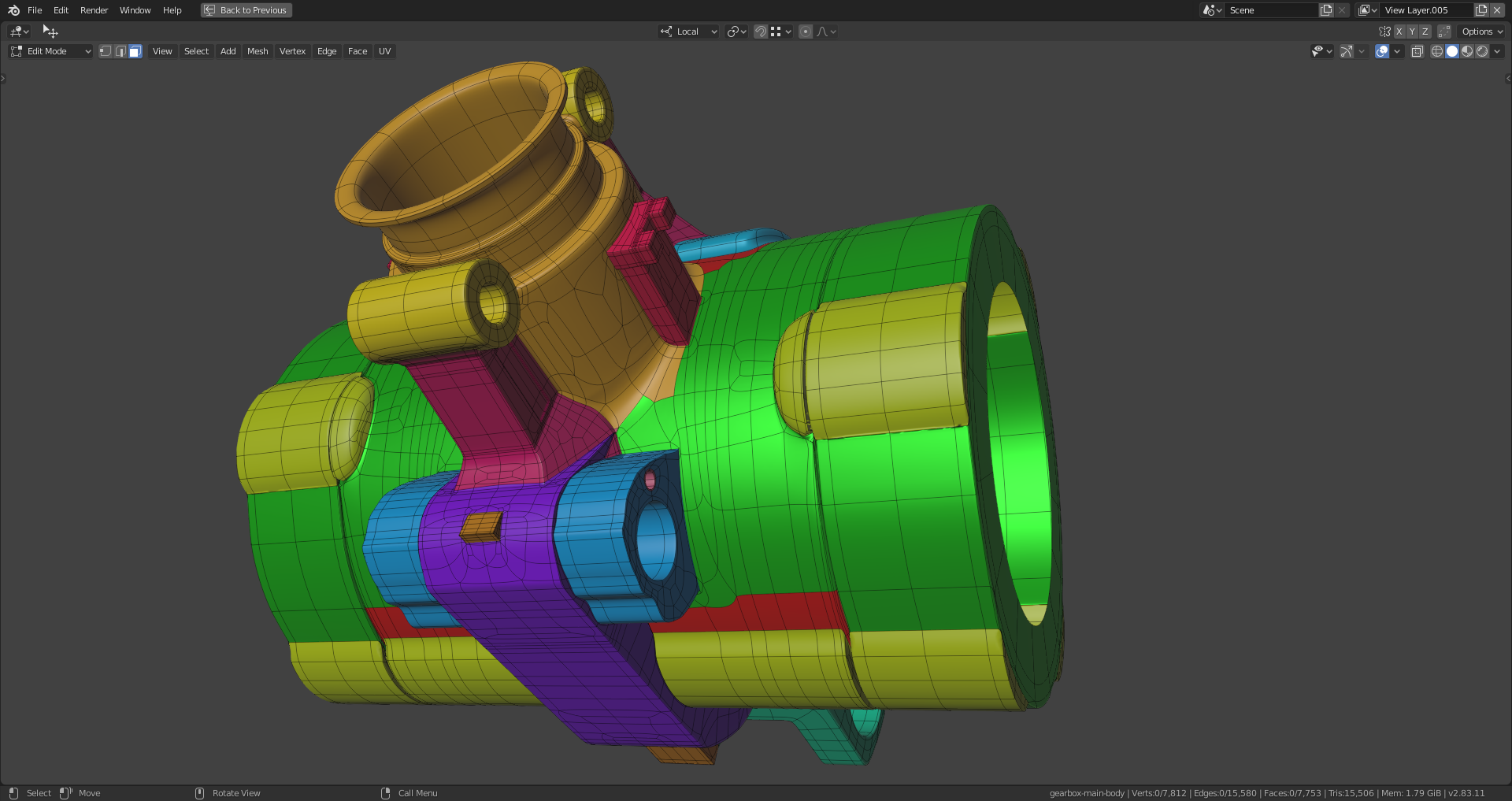
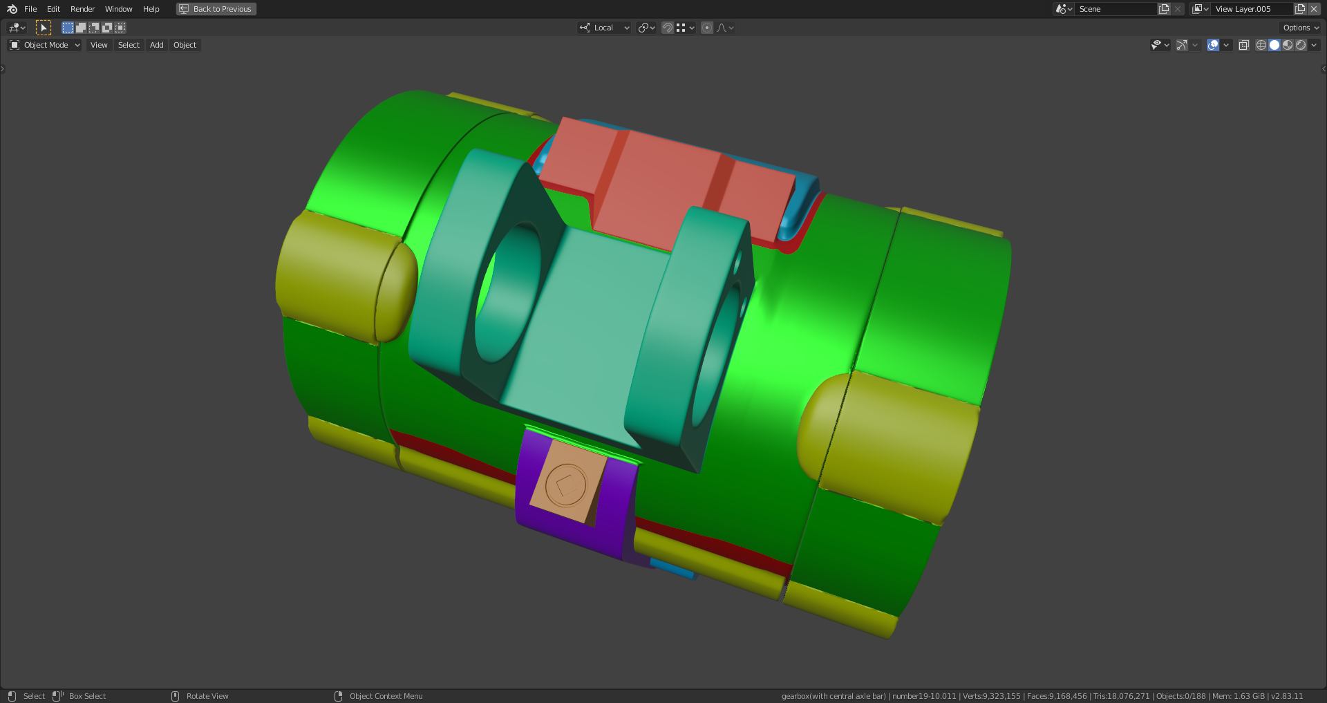
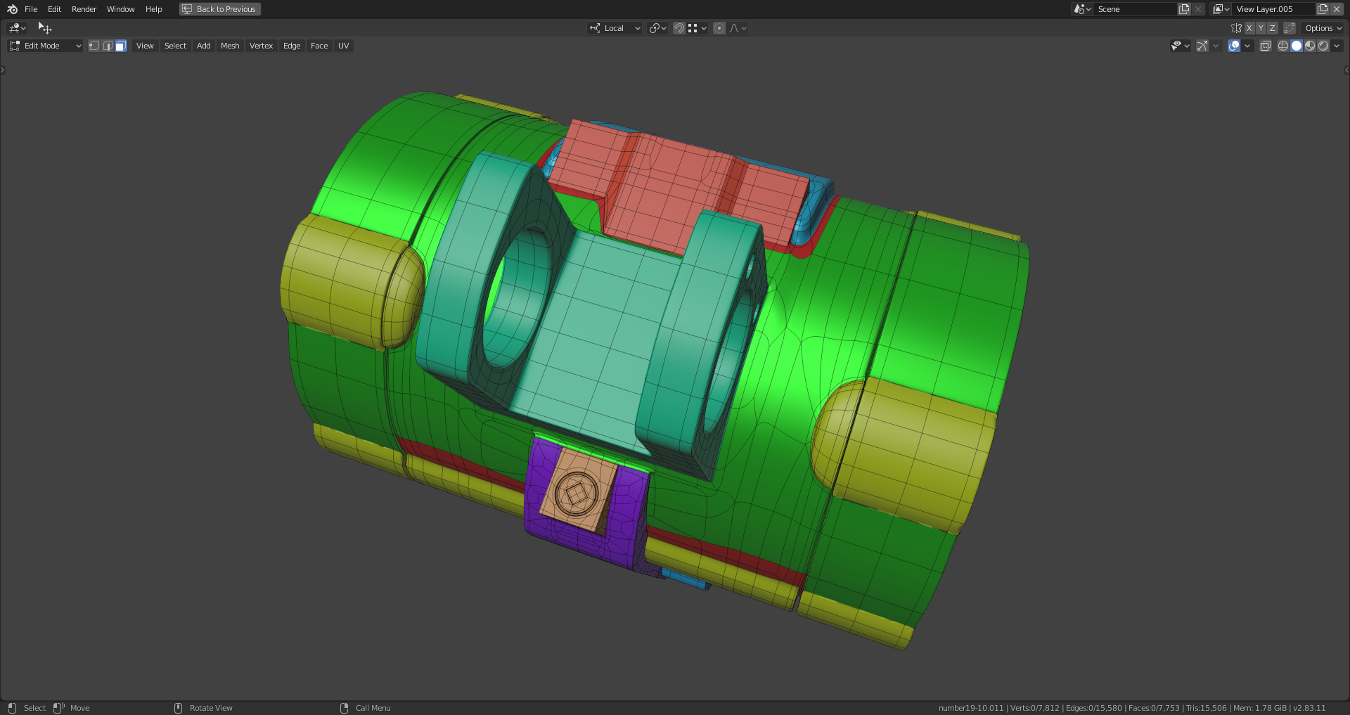
Another part connected to the left:
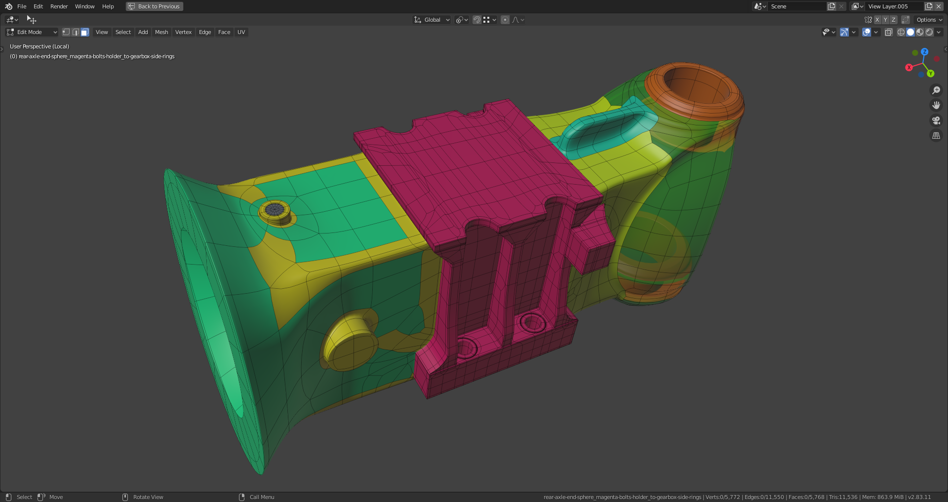
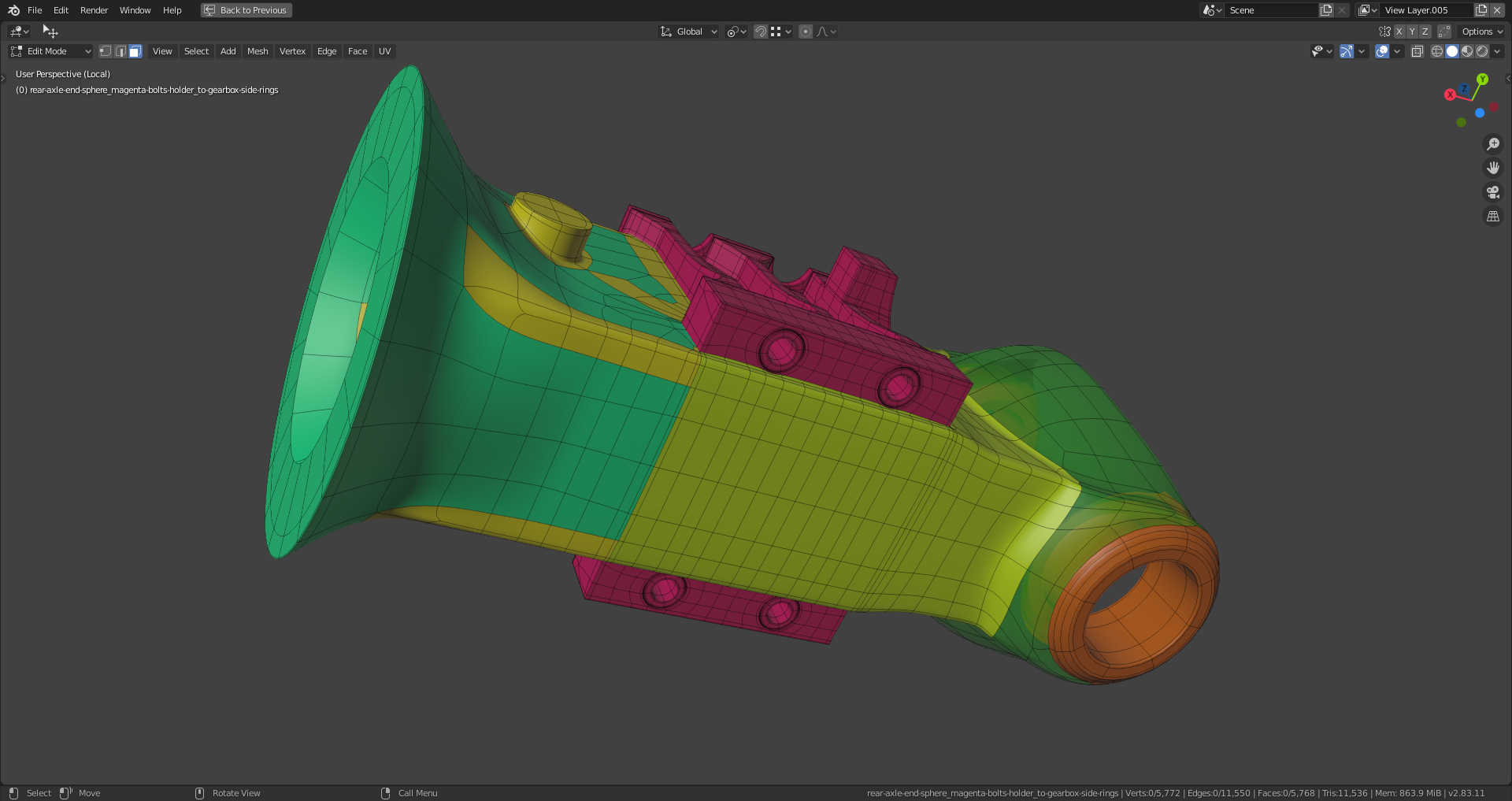
Only the gearbox side ring still has to be connected
Thanks a lot, ![]() spikeyxxx 😀!
spikeyxxx 😀!
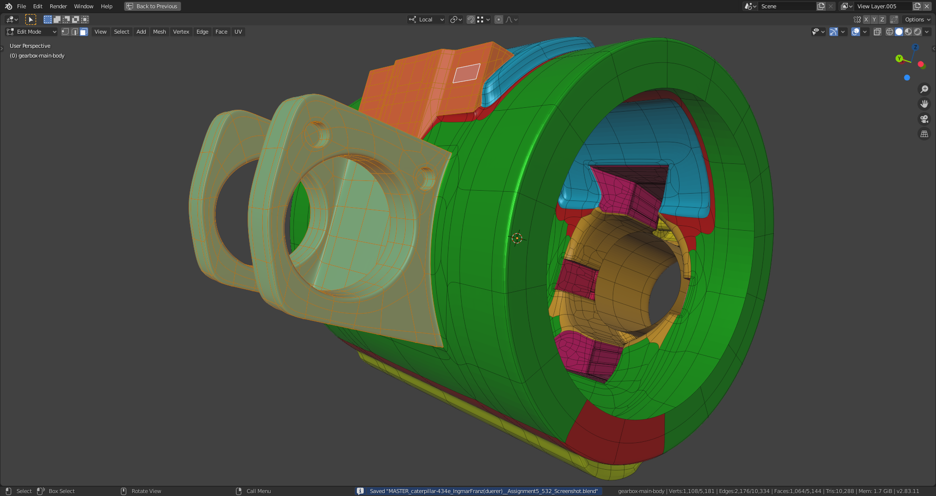
I had to dissolve many edges at the green-blue part on the left side and bring the circular shape back to perfect circles with "Loop Tools". The edges (marked with a more saturated yellow) are beveled. I duplicated one edge area and used it as snapping target for the resting three in order to get an even look.
At the magenta bolts holder, I made the edge loops run down straight from the holes to the axle bottom instead of directing them into the corners nearby because this caused a lot of edge stretching so that some faces were overlapping which was clearly visible.
The holding edges at the corners of prodtruding parts are always a challenge, escpecially when they run into curved surfaces. I have a mix of solutions which all aren't 100 % perfect (I don't know whether this is possible at all?) but some slight pinching is only visible if you come very close and I can at least live with it. Maybe you can have a look at it when I post my finished file?
The holding edges at the corners of prodtruding parts are always a challenge, escpecially when they run into curved surfaces
How true and I think you solved that quite beautifully!
Here's an example of what I did: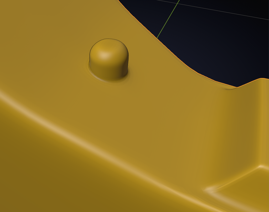
When using one of the extreme Matcaps you can see some stretching, not even a lot. But now look at the mess I made of this in Edit Mode:
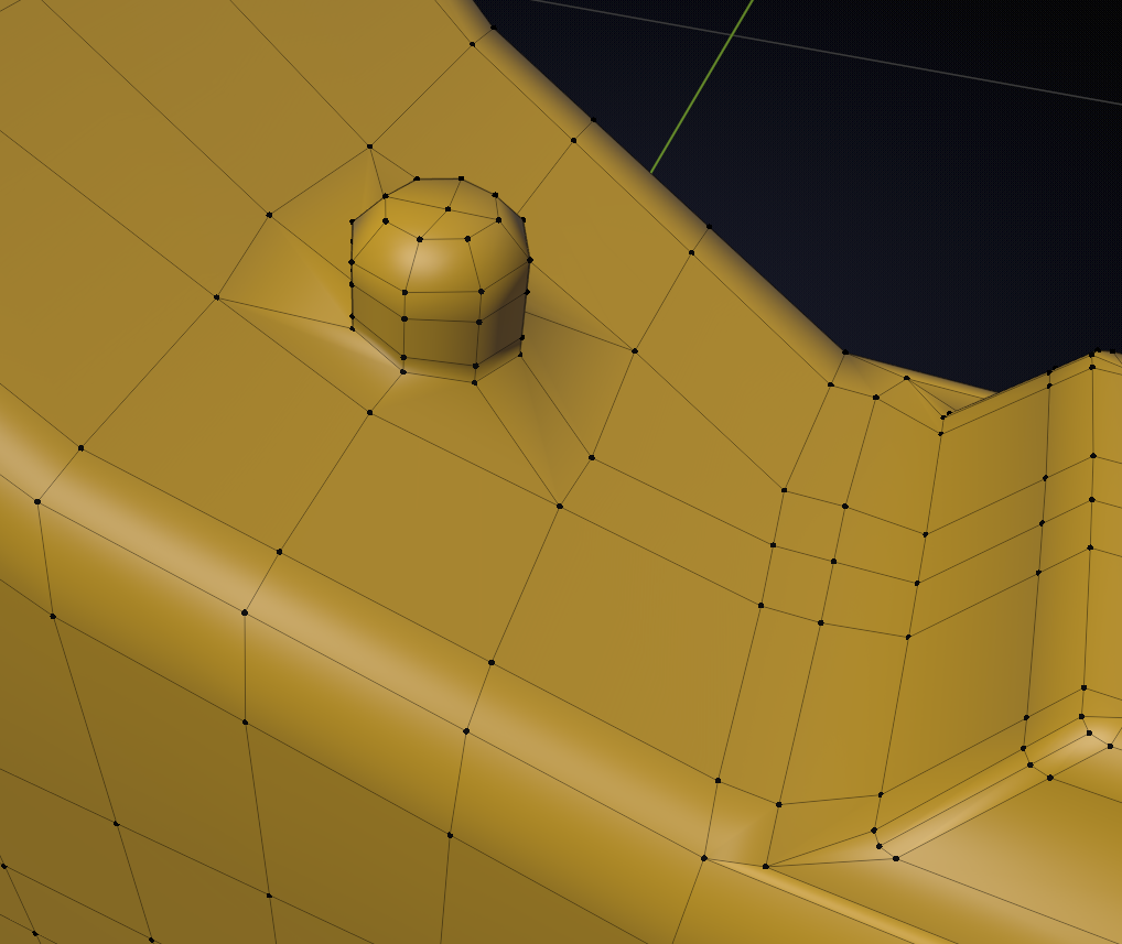
I'll be happy to take a look when you're finished, but what you've got so far looks great, I can tell that from the screenshots already.
I use the "Shrinkwrap Modifier" in order to project the outline of the cutting surface of the part that I want to connect to an object and do the same with a scaled up version of that outline as holding edge loop. Round objects are easier to connect since they don't cause as much stretching as objects with angular cutting sufaces.
I added recesses for the gearbox bolt nuts, but it's not yet all quads:
