Starting in March 2020, I began a large stream project to model a comprehensive, highly-detailed Caterpillar 434E backhoe. Please watch the first stream (first 3 minutes of abridged version at least) for an overview.
It's a straight-forward project of building a complex model over an extended period of time. The spin on the project is that I want your help to accomplish it! If I build some parts and you build some parts, we will finish this thing much quicker. Plus the contribution format will include reviews, the potential of having your piece(s) assimilated into the final model. Not to mention large quantities of XP are at stake 🤑
NOTE: This is an involved project reserved for Citizen members.

The general idea is that I kickoff stages of the project via live stream, which is typically once per month. For the time in between streams, you choose a piece of the backhoe and apply what you learned from the stream to that piece. For example, the first stream covered initial block out. So between stream 1 and stream 2, your job is to pick a piece and block it out.
This is the repeating protocol for each Assignment Period (between-streams):
I will reply to this thread after each stream with a [big] assignment post denoted by a 📣 emoji in the title. There I will clarify instructions about each Assignment Period.
We will centralize our collaborative communication between the streams and this thread. Ask any and all questions pertaining to the Backhoe project here.
DOG Manufacturing Group,
I need your advice on this part of the bucket. I think I have this side correct, but there isn't good reference for the opposite side of this should be shaped like. The part "inside" the bucket.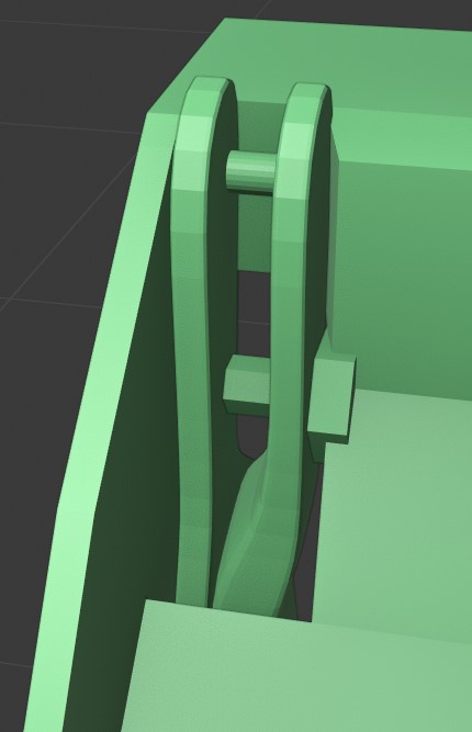 Should I just solidify this section? It would interrupt the bucket's otherwise smooth shape inside.
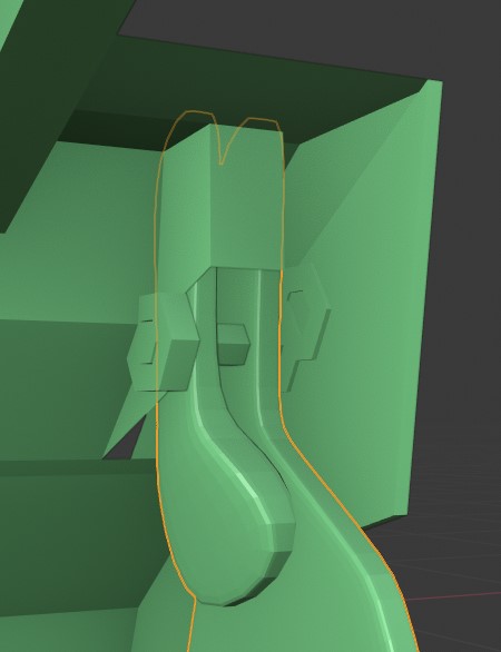
Here's what I mean, it doesn't seem right, but for the back to function it kind of has to be this way?
Maybe these "innards" are hidden by another sheet of metal, so the bucket can stay smooth?
I'm hoping there's an obvious solution I'm just not seeing.
Everyone's pieces are looking so nice!
- Parker
Here's my best guess at the moment: https://drive.google.com/open?id=12bhYTqrethkOiKs8j0Vl65yilf8usuX2
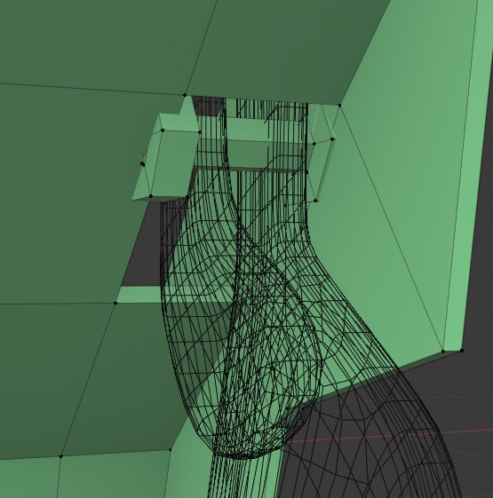
ppfbourassa I downloaded you file. That part is one solid piece up until it mates with the Hydralics where it "Forks" out into two tips. Take a loot at the Schematics link that Kent posted at the top for each part.
I found some similar bucket designs. I am willing to bet that they all share the same basic parts (manufacturing practice is to copy parts when possible)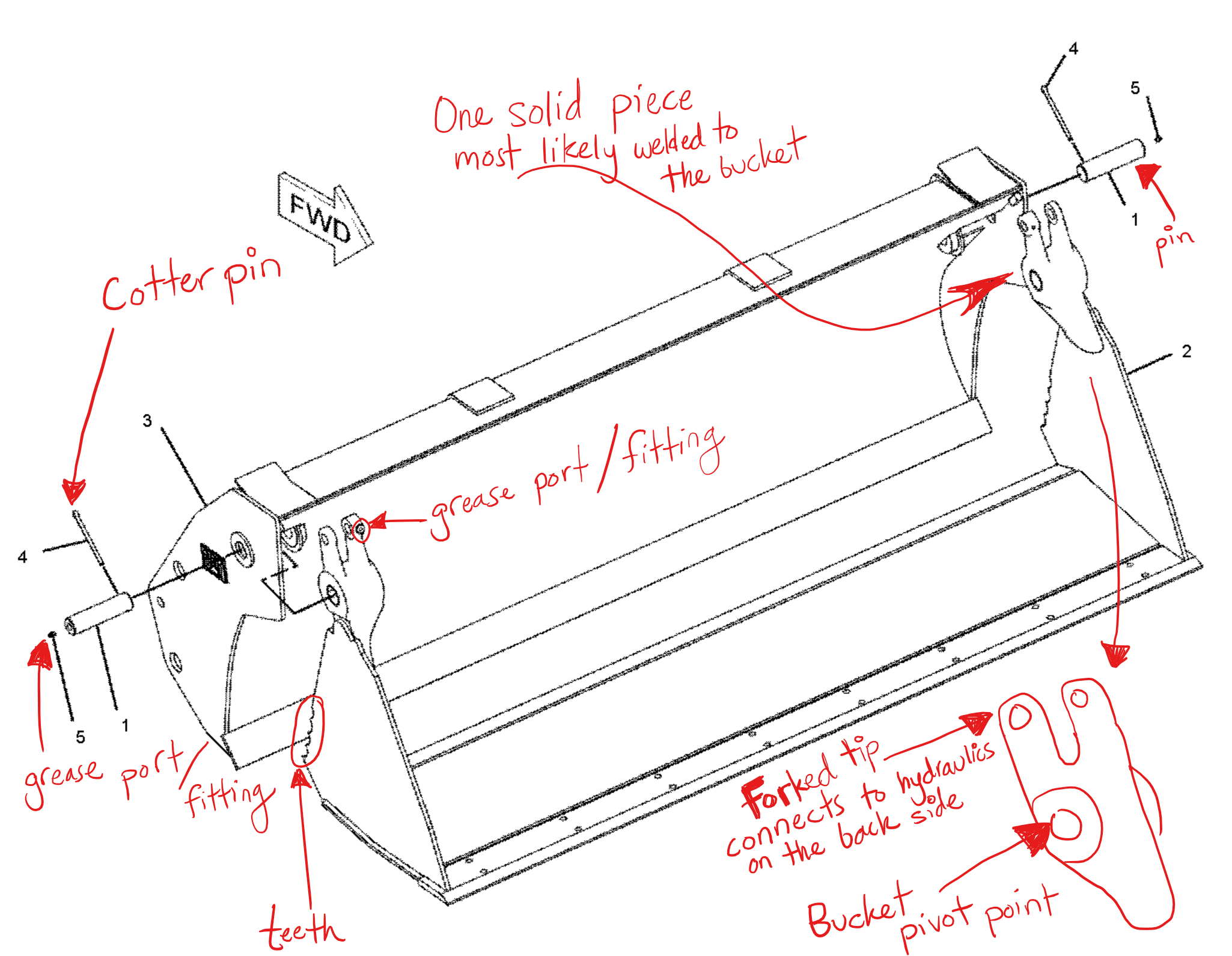
Also here is a decent back-shot of the bucket we are most likely going to try to replicate (With Forklift Forks Included!)

Link to Bucket Options: Bucket Back
Ok. I need some hard surface modeling guidance from the gurus of the group. I am having a hard time making smooth and crisp transitions from square/hard edges to circular topology. Three instances on the loader arms are causing me grief and I am unsure how to proceed. It acts like the Bevel is "bleeding" over areas where it shouldn't. I'm sure it's an easy fix but not sure what it is and I've tried a few things but with no success. I think I need maybe some more supporting geometry or "holding" edge loops in more places but maybe it's something else. It's hard to add to the circular cross section parts to give more edges to them to work with and keep them circular haha. I'm dreading that is perhaps the solution.
Link to my progress file: Loader Arms - Blanchsb
I turned on the normal matcap because I feel like it highlights this best: Areas circled in yellow are where I am reaching the limits of my "crisp yet looks soooo smooth" skills. I have my modifiers ordered like so: Bevel (with weighted edges I pick, all set to a value of 1 and percent of bevel of 5%) then Subdiv with divisions set to 2. That mod stack seems to work to keep things looking smooth yet sharp, except in these places.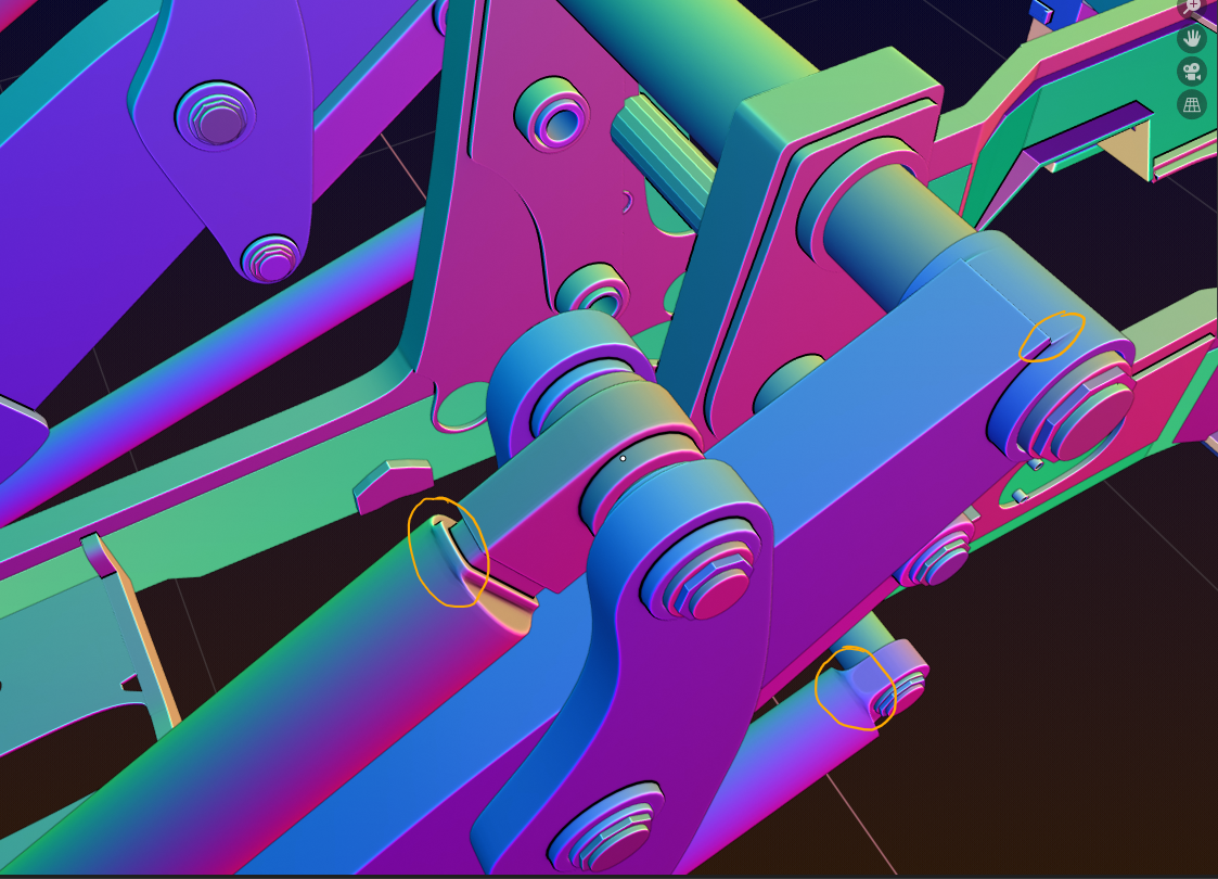
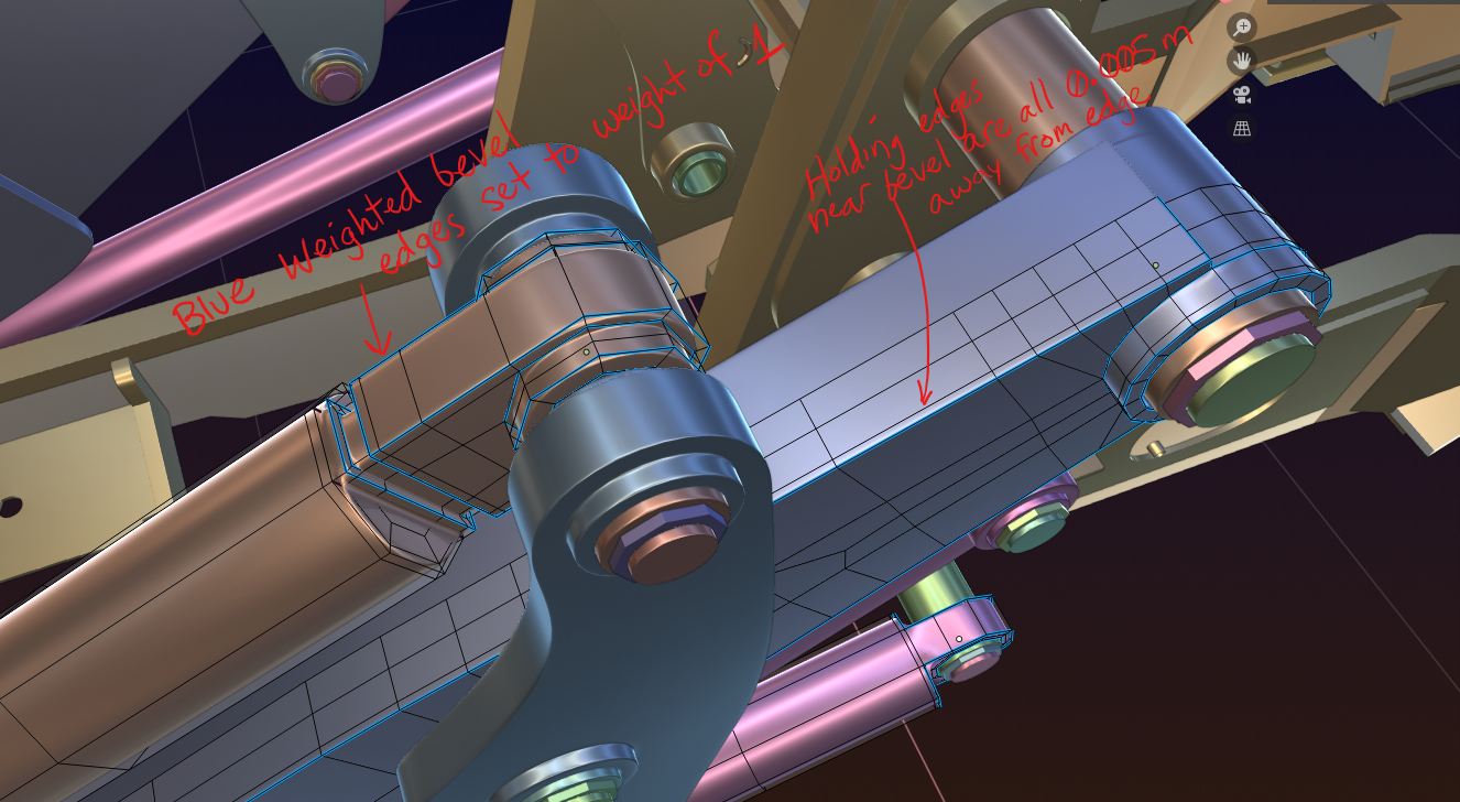
Wireframe for reference
Hi Blanch, that is looking great!
About those problem areas, this is how I would do it (maybe not the best way, but I am terrible with Creases and the Bevel Modifier with Bevel Weight only works in some cases for me...):
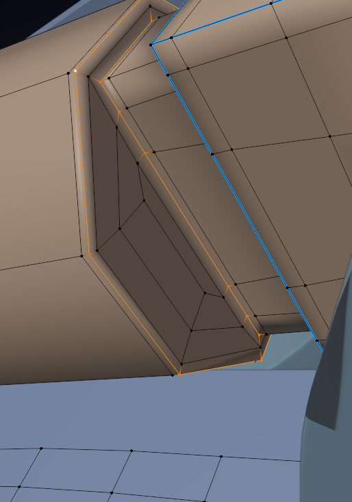
Having edge loops on both sides of the selected loops gives full control on how sharp/rounded they look, without artefacts.
The round cylinder has 8 vertices, while the rectangular piece has 12, so you need a 4 to 2 junction on both sides.
I just did this small part and only on one side, but you get the idea.
Personally, I would not use a Bevel Modifier at all, probably and only work with holding edges, but that's just preference.
Didn't show it here in Object Mode, with Subsurf, but it looks just as good as the rest of your model!
As far as I know, the biggest problem you are having, is the 5-sided pole directly on the edge:
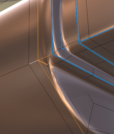
I basically moved that pole on a flat area, where it cannot do a lot of harm;)
Wait! Where did you move that 5 sided pole and can you show me? I m having a hard time thinking how to fix that part. It totally makes sense verbally but my mind is not working on the same level as you.
My brain keeps telling me "that's pole has to be there because of all of the surrounding edge complexity" but I know that is flawed thinking haha.
No you're explanation is great but I think that removes some geometry with that fix on that particular section.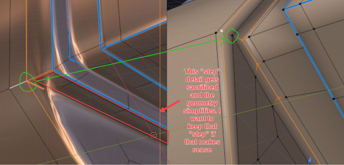
Oh, sorry I removed that detail;) I removed alot more and then re-made the connection and forgot that 'step', but that can easily be re-added with changing the topology of that area.
Just select the white face loop and do something like E, ALT+S, SHIFT Z...(or any other magical incantation that works for you):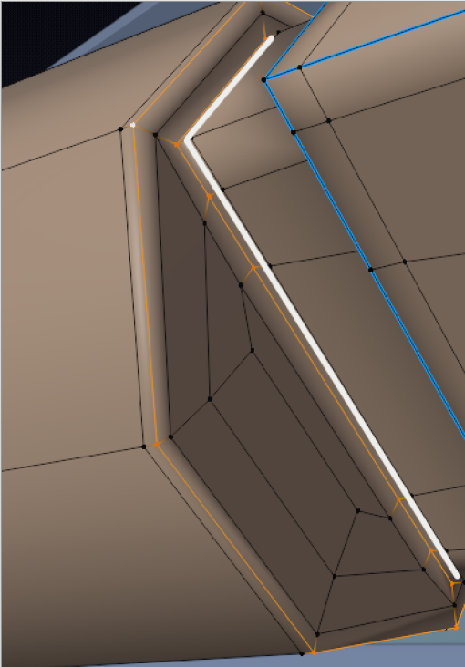
sshanr Did you ever managed to resolve this? It must've been something to do with the object origins and modifiers you have on.
I don't know what the technical term is called for that? A shoulder perhaps?
We must do the cables. I plan on putting all the extra crazy stuff that go into my part of the tractor. Since we focus on one part of the whole thing and since it's such a long time in between streams, it feels feasible to go crazy on details.
Bevel (with weighted edges I pick, all set to a value of 1 and percent of bevel of 5%)
![]() blanchsb Remember Kent said to try and aim for software agnostic modeling, meaning don't use stuff that are only a Blender thing. I think weighting the edges you pick is a Blender thing. The only modifier we should use is the SubD.
blanchsb Remember Kent said to try and aim for software agnostic modeling, meaning don't use stuff that are only a Blender thing. I think weighting the edges you pick is a Blender thing. The only modifier we should use is the SubD.
Let me try and have a look at your problem areas, that pinching in rounded from flat ares are always a headache.
I could give you something like this:
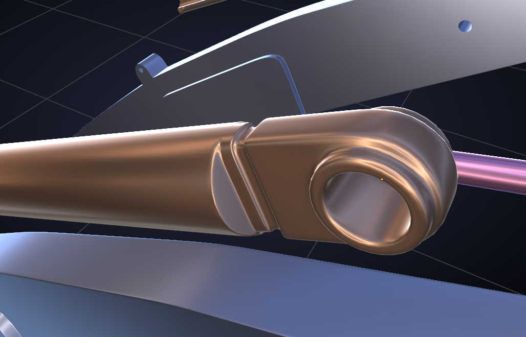
Which has this horrible topology( so far):
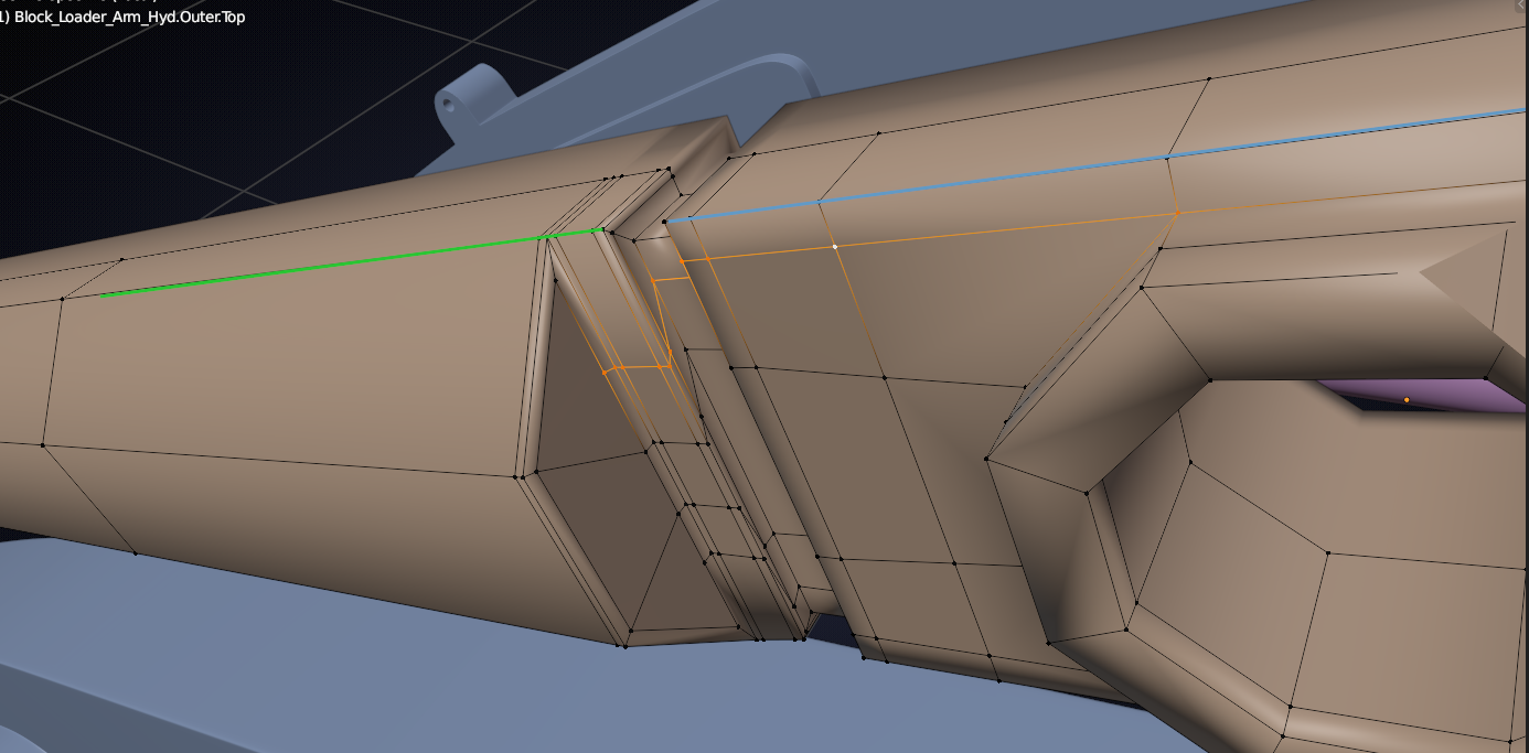
The thing is: you have a blue edge with only one holding edge to control the sharpness turning into a green edge that is supposed to be completely round, so the orange holding edge need to get away from the green edge to make that round if that makes any sense at all;)
The point is that an edge (corner) should have two holding edges, one on each side for full control...
I think you want the green part of the 'block' to be round on the top and flat on the side, but if you move the orange edges towrds the green ones, that will make the top flatter..
This is all very hard to explain in words, but I hope you get the drift.
Yes! One side flat, the other side round; And I want that Lip/Shoulder on the "round" piece in the bottom image to stick out on the side (sticking out past the edge)
Yes, sorry your answer updated on my first reply haha. I do want the cylinder section to remain a cylinder, which is why I am afraid to add any holding edges laterally along the cylinder (it doesn't subdivide as a circle anymore when I do that or I am doing it wrong). I basically want a cylinder with nice crisp cut on the side that is completely flat and everything from that point forward will have flat/square features going towards the main pivot point Pin Hole on the right side.
Your updated reply looks much more like what I am after on the top "metallic"image.