Starting in March 2020, I began a large stream project to model a comprehensive, highly-detailed Caterpillar 434E backhoe. Please watch the first stream (first 3 minutes of abridged version at least) for an overview.
It's a straight-forward project of building a complex model over an extended period of time. The spin on the project is that I want your help to accomplish it! If I build some parts and you build some parts, we will finish this thing much quicker. Plus the contribution format will include reviews, the potential of having your piece(s) assimilated into the final model. Not to mention large quantities of XP are at stake 🤑
NOTE: This is an involved project reserved for Citizen members.

The general idea is that I kickoff stages of the project via live stream, which is typically once per month. For the time in between streams, you choose a piece of the backhoe and apply what you learned from the stream to that piece. For example, the first stream covered initial block out. So between stream 1 and stream 2, your job is to pick a piece and block it out.
This is the repeating protocol for each Assignment Period (between-streams):
I will reply to this thread after each stream with a [big] assignment post denoted by a 📣 emoji in the title. There I will clarify instructions about each Assignment Period.
We will centralize our collaborative communication between the streams and this thread. Ask any and all questions pertaining to the Backhoe project here.
![]() spikeyxxx , one more question concerning the cutting-in of sharp edges into curved surfaces has come to my mind:
spikeyxxx , one more question concerning the cutting-in of sharp edges into curved surfaces has come to my mind:
How do I manage to connect the cut-in egde loop smoothly with the surrounding mesh and avoid pinches?
I am not sure what you mean exactly.
By 'beveling' the cut-in edge loop it has supporting edge loops inside and outside of the cut. It does create some 3- and 5-sided poles at the corners, but that's where the Shrinkwrap comes in and that is also a reason to have a higher subdivision level on the target mesh. Due to the fact that the original and target mesh are already at the same place the Shrinkwrap Modifier does a really good job (and the projection method is not so important I think).
As long as the original mesh has a clean topology and you create the cut from existing edges, there should not be any pinching.
I've used this method a lot and never had any pinching issues, but if you do, please let me have a look at it.
@theluthier I do have a question, about consolidating the edge loops when they're side by side, when 3 loops are side by side, you did that during the stream on my battery box and I was like oooohhh, that is some sweet technique, you can remove lots of excess geometry, I don't know if you remember, you merged them 3 into 1 and left a quad and removed lots of vertices. I was going to do that to optimize the mesh, but then I though, what if I have to change something later on? Am I committing too soon when stuff ain't done yet?
So I guess my question is, should that be left to when things are more polished and on a finished state?
![]() spikeyxxx I'm thinking at the edge of the fuel tank cap in the first of your three instruction images where diagonal edges are visible in the upper left and lower right corner of the cap outline. These edges are obviously not part of the original rectangular grid cell mesh. In this case, the cut-in edge loop has a comparatively simple structure, but what if there is a more complex pattern with a lot more of direction changes and details?
spikeyxxx I'm thinking at the edge of the fuel tank cap in the first of your three instruction images where diagonal edges are visible in the upper left and lower right corner of the cap outline. These edges are obviously not part of the original rectangular grid cell mesh. In this case, the cut-in edge loop has a comparatively simple structure, but what if there is a more complex pattern with a lot more of direction changes and details?
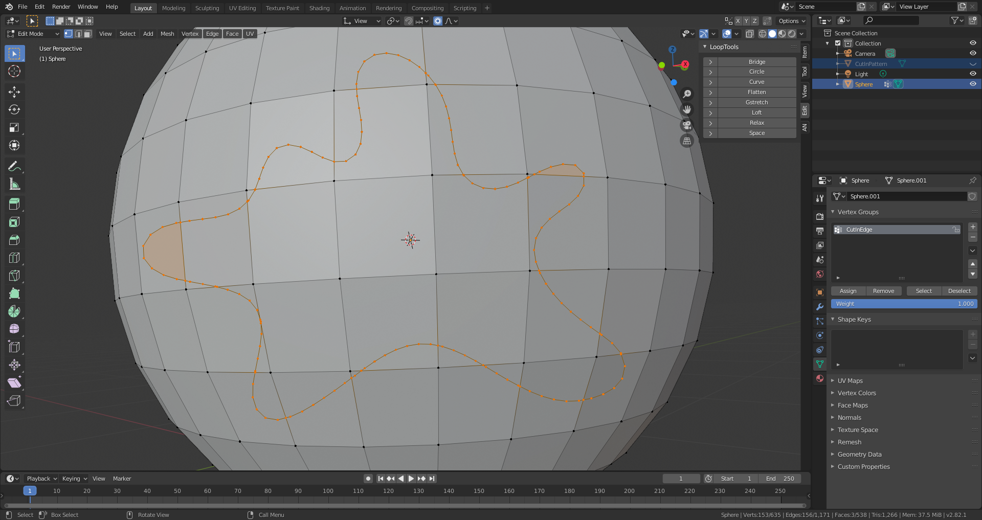
This has been cut in only with "Knife Project". Now I use "Triangulate Faces" and then "Tris to Quads", but this dosen't guarantee you a good result, as the edge beveling shows:
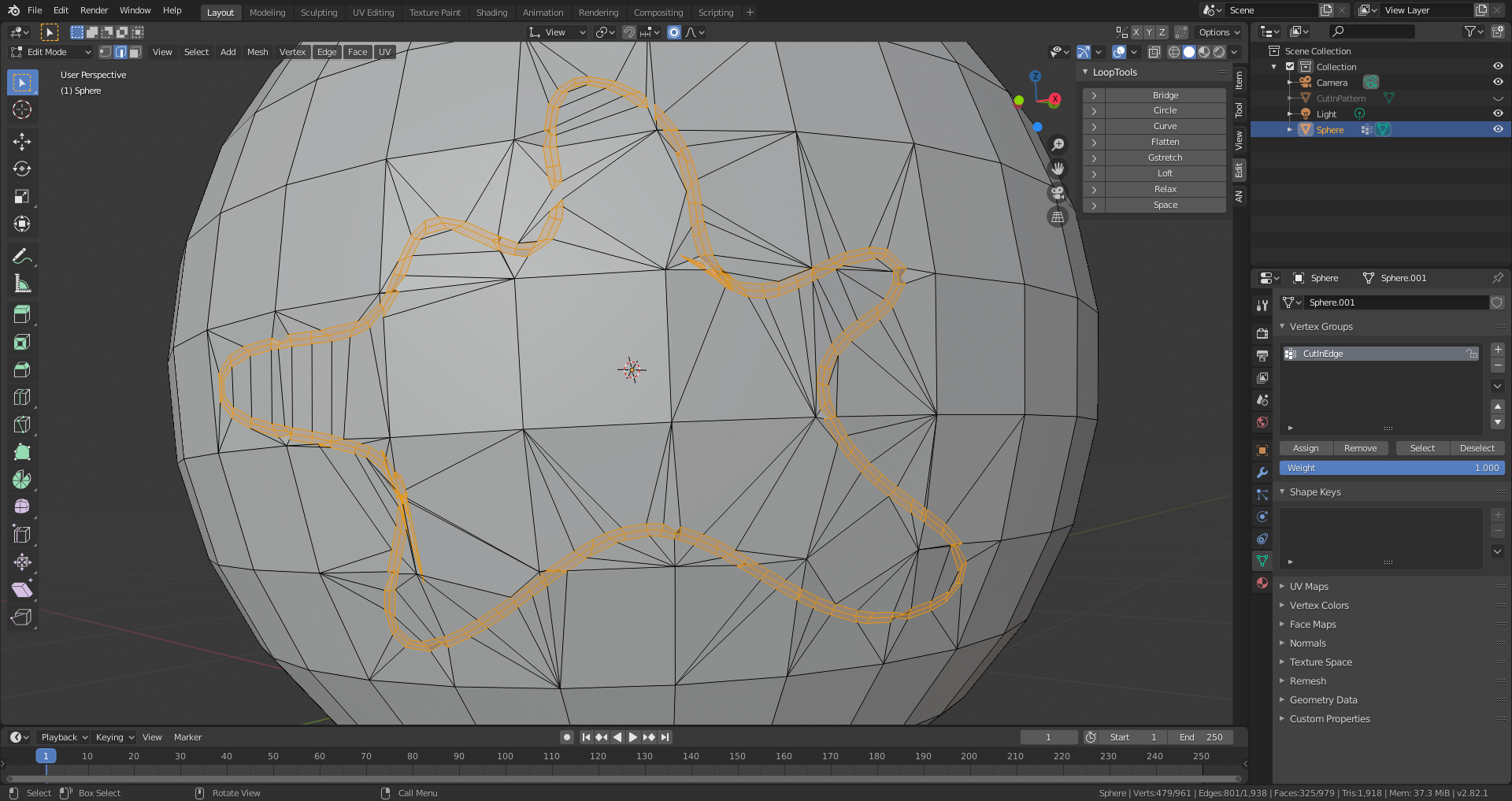
The original file with the cut-in edge can be found here.
diagonal edges are visible in the upper left and lower right corner of the cap outline. These edges are obviously not part of the original rectangular grid cell mesh
Actually they are! I just edge-slid those verts a bit to show that you can change the shape of the cap a bit, even after you created the target mesh.
As for the complex model: that is not how this was intended (did I forget to mention that you should start out with a clean topology?).
As this is a Subsurf method, I wouldn't use such an already rounded shape with 153(!) verts. make it as simple as you can to still get that shape when subdivided and then maybe subdivide the Sphere one more time and the move ( Merge) the verts of the sphere to make that shape. Or just create that (simplified!) shape directly on the Sphere by sliding some verts. That ensures that you keep the all-quad topology (at least in that area).
![]() dostovel Good question! Indeed you only want to consolidate 3 edges side by side if there's no use for them beyond a certain detail. I think this is a great talking point to cover in the next stream, but I'll try to answer generally here:
dostovel Good question! Indeed you only want to consolidate 3 edges side by side if there's no use for them beyond a certain detail. I think this is a great talking point to cover in the next stream, but I'll try to answer generally here:
In the case of your batter boxes (which look awesome btw!) there's several planar sides that don't appear to have any additional geometric detail and in some cases are visually covered by other pieces:
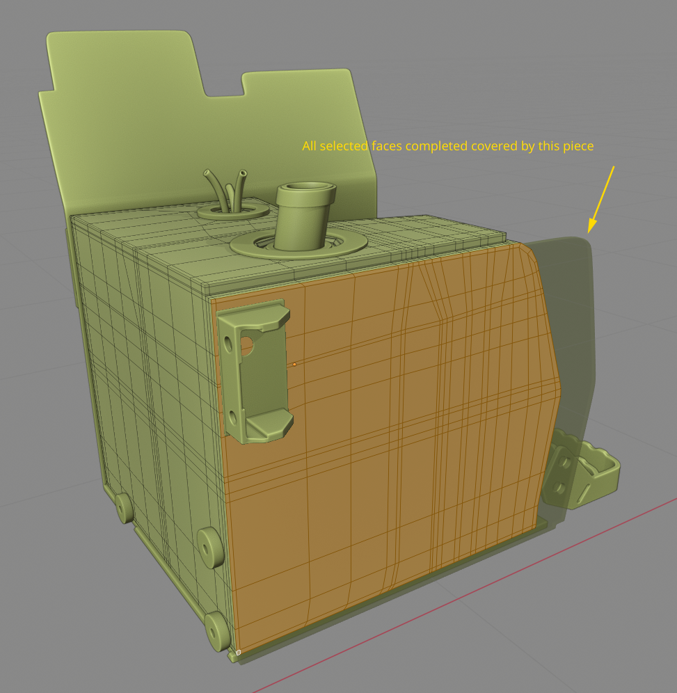
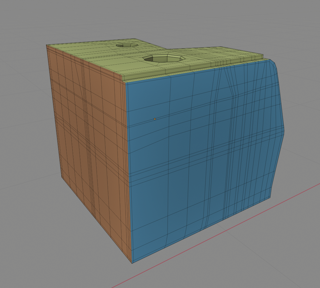
Therefore the orange and blue sides are ideal candidates for "triple-edge optimization" -- Let's call it that so we both can refer to this technique quickly.
Those are the principles that govern my decision making process about optimization. But you're the expert on this part of the backhoe, so please apply the principles accordingly!
The last thing I'll say is that this optimization process is not completely necessary. Best case scenario is it simplifies the object as much as possible for workability and should reduce render computation / RAM usage by a fraction at least. It's a "best practices" kind of thing. For a quick and dirty project I would skip this process.
@theluthier Oh my god there they are, you have them now, technology is like super awesome, one day they are in Santo Domingo, the next day in the USA. I feel like other battery boxes are like mama! come quick, your son is on the tv.
Thanks for the great answer, I like best practices, it's like an OCD to leave things super tidy up. Leave no dirty dishes on the kitchen kinda modeling for me.
![]() spikeyxxx You are absolutely right, I should follow more the "keep it super simple" (k.i.s.s.) principle . Only one question arises for me when you propose vertex sliding for creating the shape of the cut-in edge: How do you ensure that you don't loose the round shape in the area of your cut-in piece? With light inciding on your sphere at a sharp angle you can even see a very subtle surface unevenness.
spikeyxxx You are absolutely right, I should follow more the "keep it super simple" (k.i.s.s.) principle . Only one question arises for me when you propose vertex sliding for creating the shape of the cut-in edge: How do you ensure that you don't loose the round shape in the area of your cut-in piece? With light inciding on your sphere at a sharp angle you can even see a very subtle surface unevenness.
I originally selected the faces and separated by selection, then used a shrinkwrap using vertex group to get the desired result but with subsurf could not get the smooth corners. But CTRL+B and then V and a shrink wrap, so simple, genius.

@adrian2301 I had to make a lot of those panels/seams/... in the Vehicle Contest here on CGCookie:
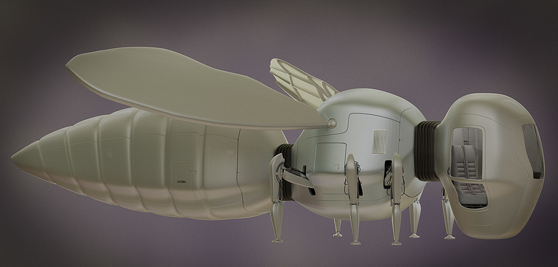
So I had to find a way to be able to comfortably do those kind of things;)
I'm sure I'm not the first or only one to come up with this technique, but I found it by myself, which makes me kinda proud...
OMG.... I'm seeing all this and going....panic. I look at what I've done and I'm going... yikes. I ended up starting over and it still looks bad...better but not like this. I'm so out of my element up in here
![]() ketre Why don't you post what you have, no matter how it looks like, and tell us where you are having trouble.
ketre Why don't you post what you have, no matter how it looks like, and tell us where you are having trouble.
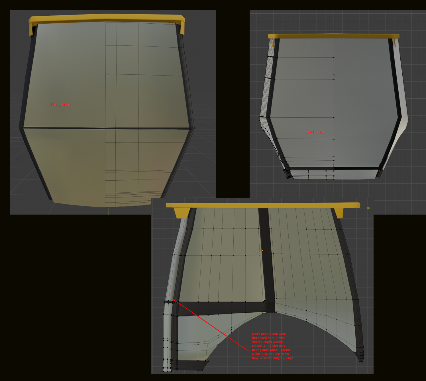
Here you go, this took me 3 day to get this... The sides bulge out in a way from the back view that they don't from the front, (not frong) lol ugh... if I take in to perspective view it doesn't look like that.
You should be proud ![]() spikeyxxx , your vehicle looks awesome, did you win the contest? Your technique defines the panels so well with clean lines. I will probably use this technique again, every time I do, I will give a little nod in your direction.
spikeyxxx , your vehicle looks awesome, did you win the contest? Your technique defines the panels so well with clean lines. I will probably use this technique again, every time I do, I will give a little nod in your direction.
![]() ketre like
ketre like ![]() dostovel says post it here, I'm sure somebody can give you some tips, as was the case with me.
dostovel says post it here, I'm sure somebody can give you some tips, as was the case with me.
'You are not alone'
(Imagine me singing that like Micheal Jackson), actually DON'T
hahahaha Imagine the uhhh dirty words flitting through my mind in my frustration. I actually turned the jams on while doing this, thinking yea imma rock this doggy....hahahah NOT
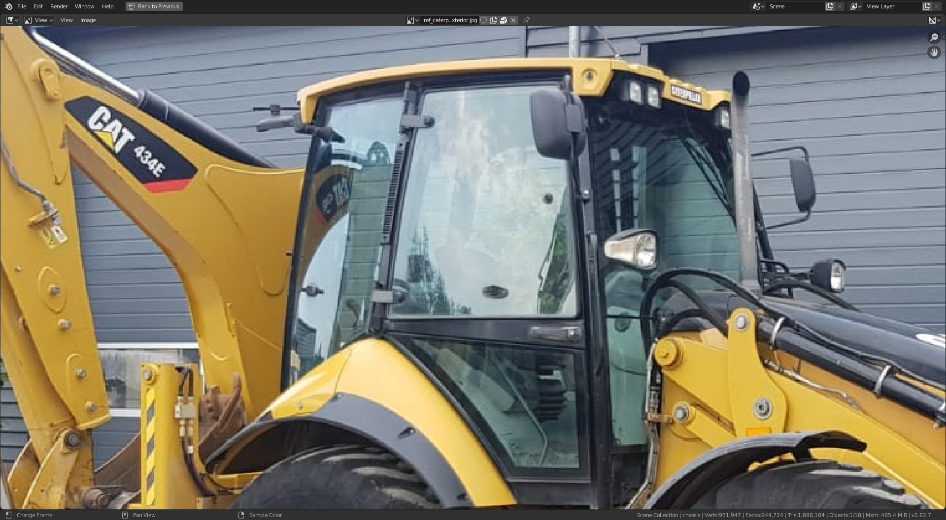
![]() ketre as you can see from this image, the left most window does curve quite significantly from top to bottom and from front (above the high point of the wheel arch (fender)) towards the bottom left corner, which would look like a bulge from the rear view. The important thing is what it looks like in 3D / perspective view, when you enter front, back or side view you switch to orthographic view which is flat 2D. Try and asses your model by panning around in 3D to see where you can smooth out any areas, maybe add a subsurf with 1 division. Keep it up. It's not a contest we are all here to learn and support each other. 👍
ketre as you can see from this image, the left most window does curve quite significantly from top to bottom and from front (above the high point of the wheel arch (fender)) towards the bottom left corner, which would look like a bulge from the rear view. The important thing is what it looks like in 3D / perspective view, when you enter front, back or side view you switch to orthographic view which is flat 2D. Try and asses your model by panning around in 3D to see where you can smooth out any areas, maybe add a subsurf with 1 division. Keep it up. It's not a contest we are all here to learn and support each other. 👍