Starting in March 2020, I began a large stream project to model a comprehensive, highly-detailed Caterpillar 434E backhoe. Please watch the first stream (first 3 minutes of abridged version at least) for an overview.
It's a straight-forward project of building a complex model over an extended period of time. The spin on the project is that I want your help to accomplish it! If I build some parts and you build some parts, we will finish this thing much quicker. Plus the contribution format will include reviews, the potential of having your piece(s) assimilated into the final model. Not to mention large quantities of XP are at stake 🤑
NOTE: This is an involved project reserved for Citizen members.

The general idea is that I kickoff stages of the project via live stream, which is typically once per month. For the time in between streams, you choose a piece of the backhoe and apply what you learned from the stream to that piece. For example, the first stream covered initial block out. So between stream 1 and stream 2, your job is to pick a piece and block it out.
This is the repeating protocol for each Assignment Period (between-streams):
I will reply to this thread after each stream with a [big] assignment post denoted by a 📣 emoji in the title. There I will clarify instructions about each Assignment Period.
We will centralize our collaborative communication between the streams and this thread. Ask any and all questions pertaining to the Backhoe project here.
Yeah sshanr They are technically grown-up toys haha!
Don’t pay any attention to the DOG image on my submission, that was NOT a decal by any means I was just trying to figure it out last minute and ran outta time.
@theluthier One thing I wonder if you could cover during the live stream would be how to add a circular cut-out on a rounded surface that will not cause the main rounded surface to “deform” weirdly with subdivison. There are a lot of Grease Fittings on my loader arm parts and most fittings will screw into threaded holes that would go from the outer part curved surfaces all the way to the pins “pivot points“ for rotation, the curve surfaces are typically the areas of least metal thickness and make for good locations to drill out material. High areas of friction require regular greasing applications to preserve their integrity So grease fittings or “grease ports” are placed for ease of adding lubricant to high friction areas with a grease gun.
Jonathon posted a video that I believe is relevant but it probably means most of my low poly parts will need an applied subdiv to use the trick a little better? Or maybe you could just show how to do one during the live stream. You’re probably going to have to figure that out as well. We will also probably want to use the “same” size grease port fitting across this DOG too so maybe having one built with help anyone else who has need to use them?
Jonathon’s video on youtube is posted below.
https://www.youtube.com/watch?time_continue=127&v=RGQgqlVq_Cg&feature=emb_logo
Your loader arm is looking great, Shawn. I'll be happy to cover the circular cuts in rounded surfaces bit. Could you snap a screenshot of the "grease port" that you're describing so I can approach it most relevantly?
but it probably means most of my low poly parts will need an applied subdiv to use the trick a little better?
Unfortunately applying a level of subsurf is often the only option, depending on the level of curvature. Looking at your arm pieces I don't see much curvature...so I'm curious about the specific area you're referring to.
![]() blanchsb , that's exactly the link I just wanted to post now 😀! But I'm just 16 minutes too late 😉 .
blanchsb , that's exactly the link I just wanted to post now 😀! But I'm just 16 minutes too late 😉 .
I've also found this video usefull, since the guy here cuts an svg-path into a sphere where he uses a "Curve Modifier" in order to minimize distortions of the path before projecting it onto the sphere with the "Shrinkwrap Modifier".
![]() blanchsb , I've used Inkscape in order to trace the "Dog" logo for the wheel hubs, since the orginal "Cat" logo is 3-dimensional, too. The only problem is using it with a "Mirror Modifier", so I applied the modifier and rotated the logo manually.
blanchsb , I've used Inkscape in order to trace the "Dog" logo for the wheel hubs, since the orginal "Cat" logo is 3-dimensional, too. The only problem is using it with a "Mirror Modifier", so I applied the modifier and rotated the logo manually.
@theluthier this also begs the question: Would this be a good use case for using the coveted MultiRes (this isn’t a “skinned” mesh I suppose but I wanted to know if it had a use case here Since I don’t have much geometry to work with, I have never used multires.......ever).
yeah I’ll try to get the grease port fitting posted here after work today. I’ll also show where mine are going to be needed to be installed based on ![]() jakeblended ’s find of the schematics (and my own special access). and as a complete side note, how do I “quote” someone. I’m on my iPad right now and not sure how that works.
jakeblended ’s find of the schematics (and my own special access). and as a complete side note, how do I “quote” someone. I’m on my iPad right now and not sure how that works.
1. I’ll definitely watch that video later. Thanks!
2. I am using Afinity Designer to make the DOG logo (I think ![]() dostovel logos should be the officials but I drew that up around the same time and I may want to do a special background on the loader arm logo because for the cat logo it has a unique shape there. Using the decalMachine add-on is super handy putting this on original/mirrored objects and once I figured it out it was extremely easy to use, plus it has the feature to add 3D detail and makes use of paralaxing. I think I’ve purchased most major add-on’s and am itching for opportunites to use them to learn how to add them to my workflow. I know the mirror modifier has a flip U or flip V feature as well that seemed to work really well for me.
dostovel logos should be the officials but I drew that up around the same time and I may want to do a special background on the loader arm logo because for the cat logo it has a unique shape there. Using the decalMachine add-on is super handy putting this on original/mirrored objects and once I figured it out it was extremely easy to use, plus it has the feature to add 3D detail and makes use of paralaxing. I think I’ve purchased most major add-on’s and am itching for opportunites to use them to learn how to add them to my workflow. I know the mirror modifier has a flip U or flip V feature as well that seemed to work really well for me.
Would this be a good use case for using the coveted MultiRes
If anyone covets multires...it's me haha. Theoretically yes, multires could be used to add smooth subdivisions AND fine tune pinching via sculpting. It's a clever approach in fact.
But It's not a common solution and slightly complicates the setup. Imagine doing this for *all the pieces on this backhoe* 😵
Typically you can get a simple subsurf modifier to do what you want with enough finagling, at least to a satisfactory level. Only in the most bothersome situations would I add a multires modifer to manually smooth out pinching.
Had to Google the word 'covet' and found this:
"Thou shall not covet" is the most common translation of one of the Ten Commandments!
Funny how educational learning 3D actually is;)
Lol. It is technically coveted because Kent wants it to work on 2.8 badly. I hear there is a semi-stable release on 2.83 on the rumor mill. ![]() spikeyxxx is this true?
spikeyxxx is this true?
Superfresh info about Multires: https://www.youtube.com/watch?v=ZENK_ycrN_M
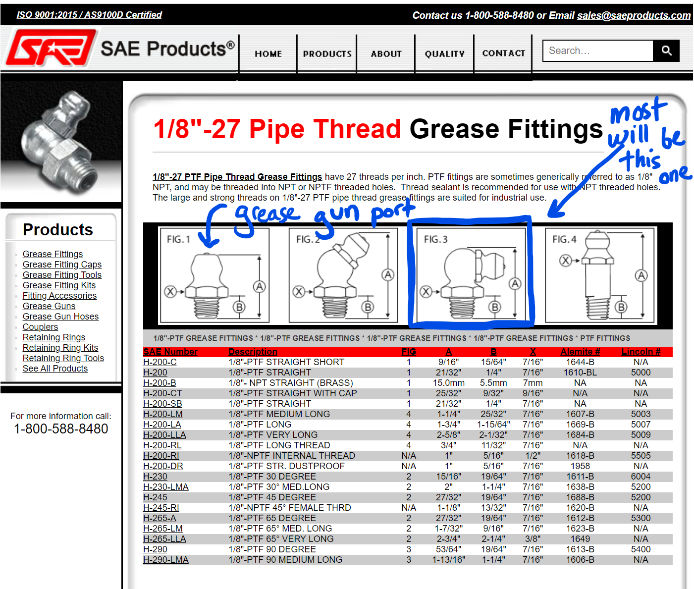
@theluthier okay here is the examples of the grease fittings and adapters that get installed into my curved surfaces that have pinned hinges. (Now I'm thinking of the children's song "I'm all made of hinges")
and here's some info on the specific grease fittings posted below. The 90 degree fittings are mostly used when I zoom in on the diagram for the loader arms.

There's also going to be a bunch of hydraulic fittings as well on all of the hydraulic parts that will share the same modeling lesson/technique. Hope that helps for the lesson.
Sorry for the radio silence, guys!
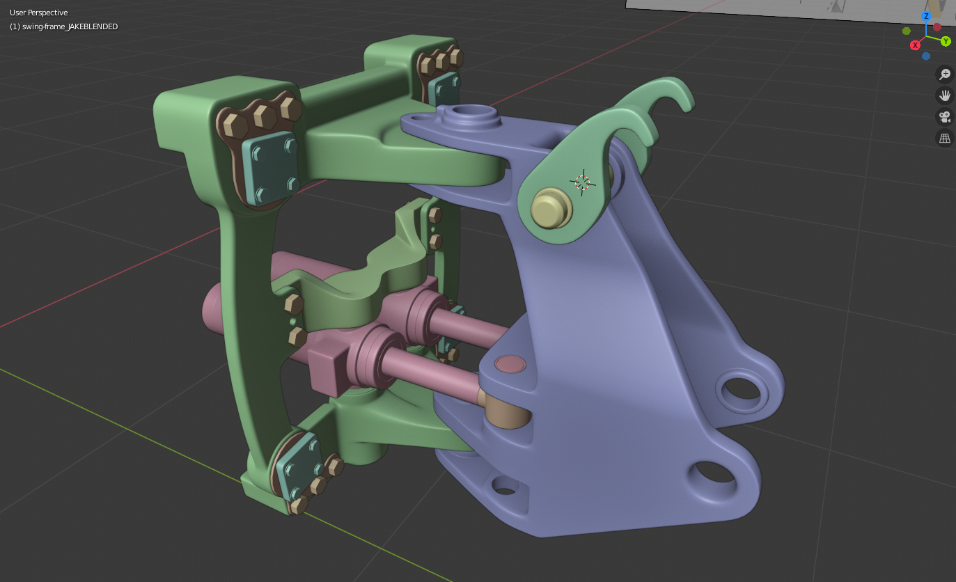
Here's this month's detail work. I'm a little anxious that it might be visually underwhelming, and I'm glad Kent set a minimum of 25% completion, because there was a whole lot of work to do for what might not look like much visual progress since my initial block:

Because of the design inconsistencies I mentioned last month, I ended up having to reblock all the major components from scratch - AGAIN! I had hoped I could just use the first blocks that I made and maybe just simplify the mesh and reshape them, but no dice there sadly as the correct pieces were ultimately just too different. It soaked up a lot of time to build all that again, but on the plus side I am much happier with my topology this time around.
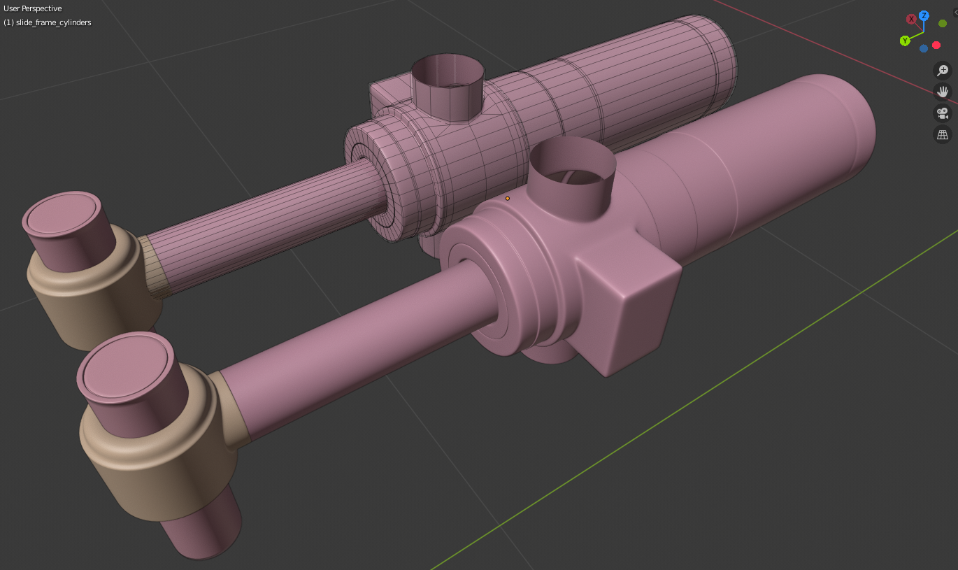
The only components from my first month that I was able to actually reuse were the hydraulic cylinders. But, I did give them a work-over to clean up some topology issues especially around the vertical "round" parts - I had not made a very good intersecting cut with my first blockout - and I retooled the surface to make it more closely match the cylinders in my reference photos.

But at any rate, with all of this work, basically almost all of the major and minor hard-surface parts are done for this part. But, there's still plenty of work to go. I estimate that at least two-thirds of the remaining work I have to do is going to be hydraulic apparatus - hoses, pipes, and fittings, and the small brackets that hold all of them. There is a LOT of it. It's like someone just dumped a whole basket of snakes into the back of the backhoe. Really big snakes. But, I'm confident it's nothing I can't handle and I'm looking forward to it!
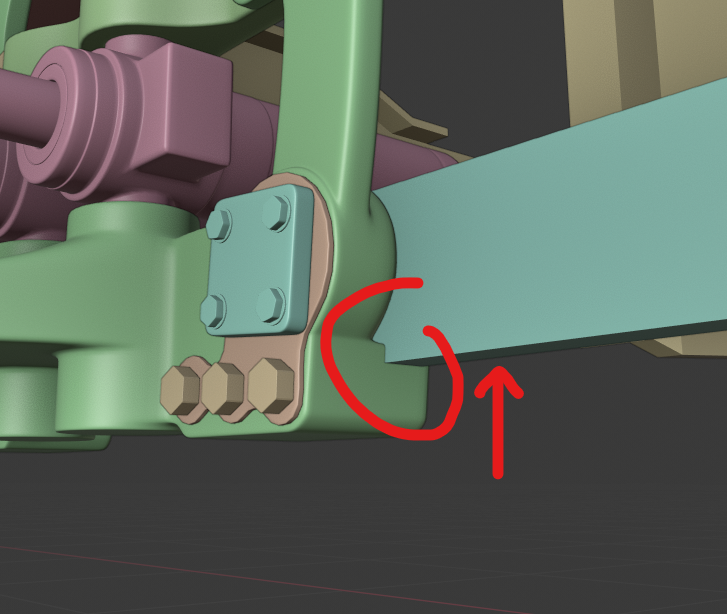
@adrian2301, I know that you've made a lot of progress on the frame, but all I have is the original one that came with Kent's stream 2 download, so I don't know if you've changed anything around this part or even if you've been waiting for me, so I only have this request with regard to your frame: if you can, I'd like you to raise the lower-most "slide rail" (that's what I've decided to call it) just an inch or so, enough so that it clears this part:

You can see where it intersects the small "ledge" that sticks out the back of my slide-frame there. Raise the whole rail if you can, because each of the two rails AFAIK should be the same height top to bottom. I think you should be able to raise it just enough to clear that, without intersecting the hydraulic cylinder above; if there's problems, I can address them afterwards. That's the only change needed on my end!
@theluthier I think you'll probably need to move your digger arm so that the bottom hinge pin lines up with the holes on the swing-frame, and that's pretty much it. There shouldn't be any design changes needed from either of us by this point. The bottom end of your boom's piston should clamp on to the upper hinge pin. You can probably just rotate and move the piston itself rather than the whole boom to make it fit. Unless you want the "latches" on top of the swing-frame to be engaged with the small cross-pin there - it's up to you, and you can just rotate the latches as needed if so - if I need to do any remodeling of the latches to get them to fit right just let me know. The latches are only supposed to be engaged when the digger arm is "stowed", so if you're modeling the arm to be extended in any way I suppose they would stay unlocked.
The blend file is in my OneDrive if anyone wants it - it's the "swing_frame_02" file. ppfbourassa I'd love to make it into your reel if there's time!
It's been so awesome watching the progress everyone is making. I feel like finding that site with the part drawings is like my biggest community contribution since I've joined CGCookie. :)
We're on a roll everyone, let's keep it going!
That is perfect! I've actually been looking around for a decent close-up view of some grease fittings; these drawings are even better.
Perhaps another pain point that everyone will probably appreciate being covered is how to line up circular parts so that they are concentric with others.
I know blender is not really a CAD program and the snap to an object’s circle-center circle ⭕️ is not a built in feature like other professional 3D cad software.
@theluthier Maybe a quick tip on how to align parts that are all concentric to each other would be helpful for the DOG Pound? What do y’all think?
There are a lot of hydraulic/mechanical fittings and hinges on a lot of these parts that are all going to need to be lined up. I know eye-balling-it is the artist way for a lot of things but the engineer in me cringes to do that over and over again haha, maybe it’s just me and I’m being overly critical of my own workflow though.
One rather hard exercise I have found is lining up 1 object with 2 other objects without deforming the mesh terribly. Say there are two hinges, one at each end, and you need to line up both ends to other hinged parts of the assembly.
Maybe this is too late to discuss this though. Just figured I’d throw this idea out. I spent way too long trying to solve this particular problem on my own and told myself “there must be a better way” and “I’m missing something”