Get it? Math Lab.... sounds like Me.... Lab?.... No? ok
So ![]() spikeyxxx you're like a super mathematician, I'm doing the Blender Cloud Procedural Shading course and it is super heavy dense in tough, difficult and impossible things and worst of all there's like a lot of math involved. I wanted to use this to bother you a lot and ask you math questions when it comes to procedural shading.
spikeyxxx you're like a super mathematician, I'm doing the Blender Cloud Procedural Shading course and it is super heavy dense in tough, difficult and impossible things and worst of all there's like a lot of math involved. I wanted to use this to bother you a lot and ask you math questions when it comes to procedural shading.
The course is good but Simon goes way too fast and doesn't get into the really basics and assumes you know what happens mathematically under the hood.
*WARNING, HERE BE MATH*
I would expect the render to get it right, but you should at least set the Color Management to Standard...

Spikey you should be teaching this stuff. It turned out identical. I here by award you with the CG Cookie honorary master achiever.
My goal is to get to the point that I understand this and make it on my own. At least to start with. Ok, back to trying to understand the basics.
![]() dostovel just wait until
dostovel just wait until ![]() duerer finishes explaining the main shape and then we are already mostly done ;)
duerer finishes explaining the main shape and then we are already mostly done ;)
I repeated a small version of the main shape to the left of it as a Fake shadow.
You already know how to make a diagonal gradient, so basically you can also already make those two light streaks, well, almost...Let's finish the main shape first and then I will guide you through the process (and I am sure that ![]() duerer will help with the explanations)
duerer will help with the explanations)
Well, there's also snapping your mind to this way of thinking, I don't know how you guys arrive at this conclusions to do this. That is only achieved with practice and getting into this mindset with lots of trial and error. Right now my mind sees a shape and it tries to follow the contour like if I have a pencil and I want to draw a straight line. But that's not how it is reached when it comes to using nodes, it's like you have to hack it into existence, almost in a boolean way. It's strange to my mind right now, but I'm slowing getting there. I need to take it one small step at a time, trying out simple shapes and getting more complex each time.
Ok no WHAT!? How subtracting X gives you that perfectly clean cool slant? What is happening there?
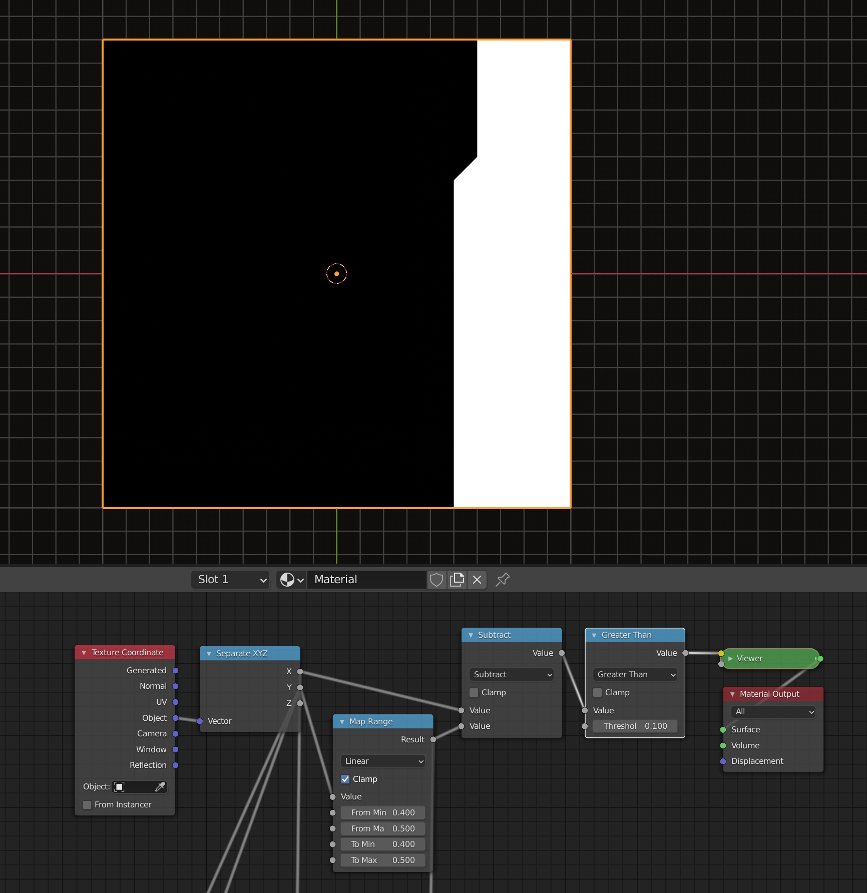
For the bottom end I set "From Min" to -0.5 and "From Max" to -0.4 so that, as in the case of the top part of the protrusion, I'm climbing upwards the Y axis within the bottom protrusion interval. During this Y upwards movement, the bottom part of the protrusion goes into the direction of positive local X (from the current viewpoint to the right) whereas the movement at the top part of the protrusion goes to the left. This inverted direction in the bottom part of the protrusion makes it necessary to swap the "To Min" and "To Max" values from the "Map Range Node" for the top part of the protrusion:
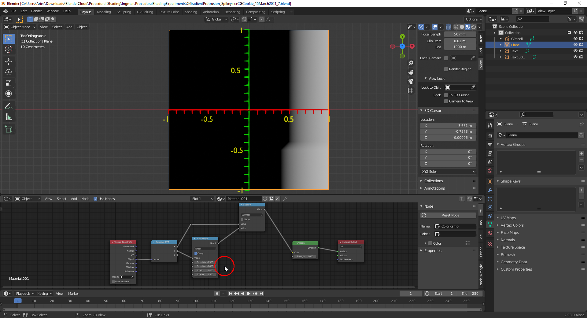
End of part 3
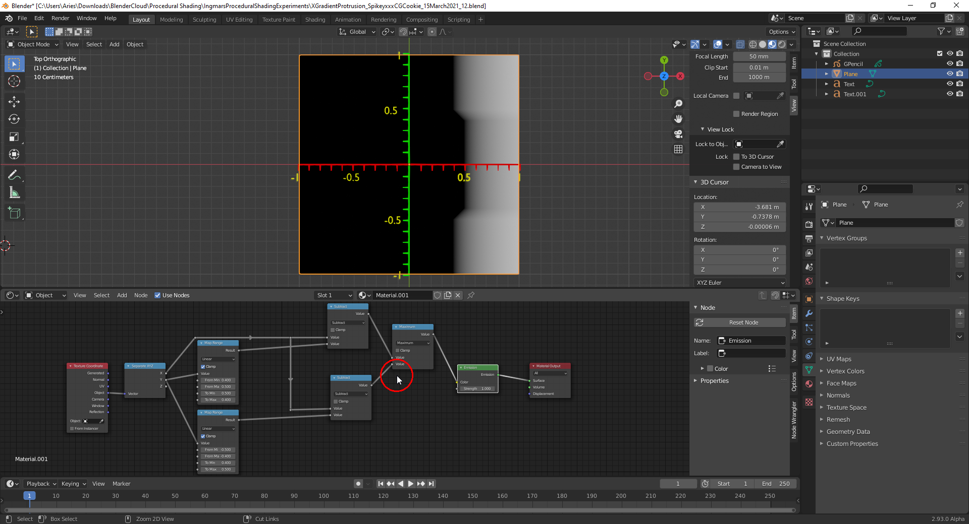
Now, both procedural textures from above can be combined with a "Math Node" set to "Max" so that only points that are black in both textures will be displayed as black in the final texture:
This can be sharpened with a "Math Node" set to "Greater Than" and a "Threshold" of 0:
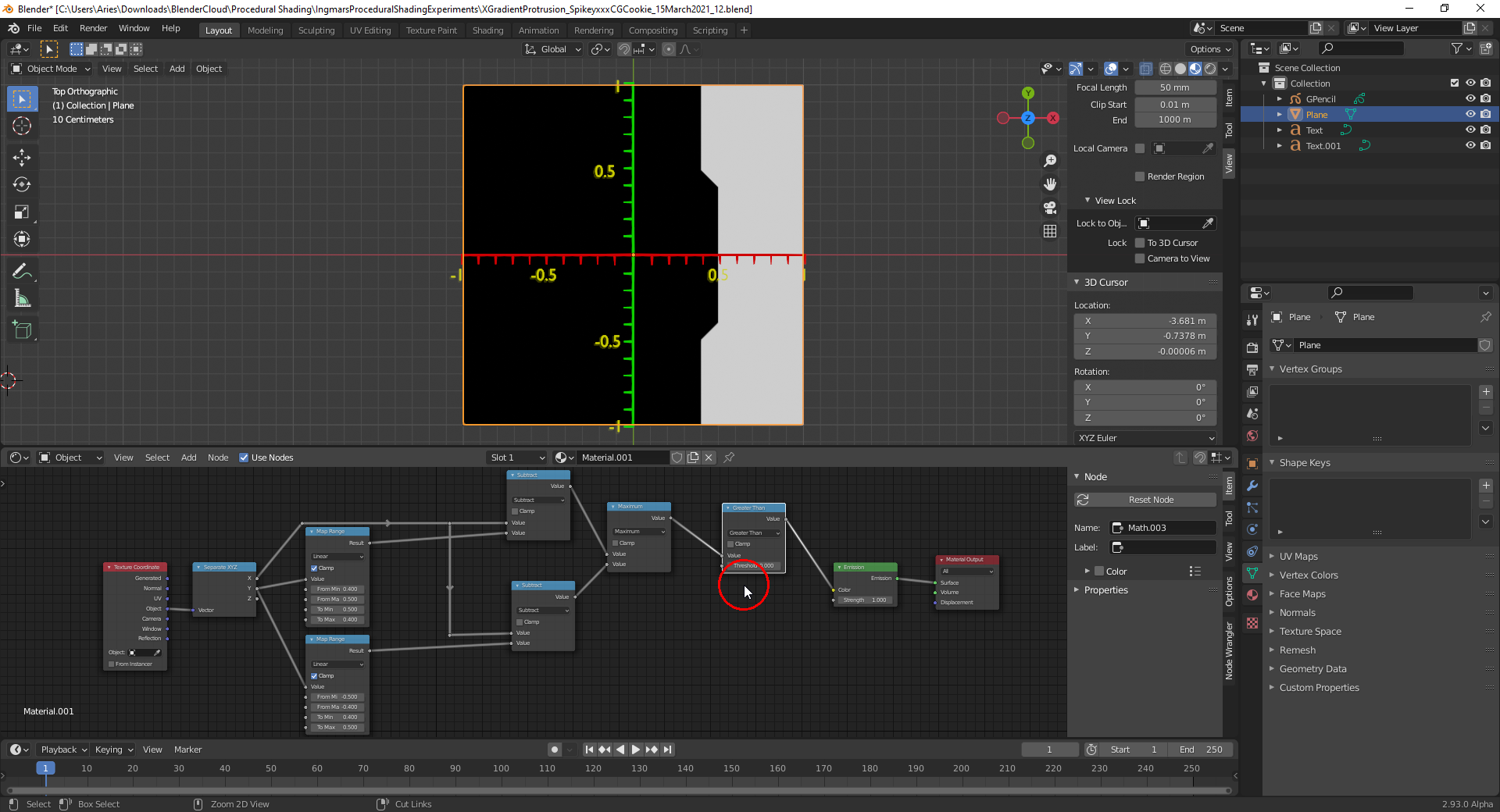
End of the final part 4 😌😉.
PS: File is here.
Well, there's also snapping your mind to this way of thinking
That is sooo true! Completely different from modeling some shape. Took me some time too to get here and I am still way behind
guys like Simon Thommes and.....luckily many share their knowledge these days.
Now, how did you calculate that those are the exactly values?
![]() dostovel I got them all wrong!
dostovel I got them all wrong!
If you look at the top image, you go from -3 to 4...those are 7 'stops'. Below you go from -1 to 2, which are 3 'stops'.
Going from right to left in the bottom image, you need 7 stops, that are all the same distance away from each other to cover a total distance of 3...which makes the distance between two stops 3/7,...and 7 of those stops would yield 7 * 3/7 = 3, which is exactly what we wanted!
so, again from right to left on the bottom image, the numbers would be 2 (2 -3/7) (2-6/7) (1-2/7) (1-5/7) (-1/7) (-4/7) -1.
Do not read what comes next!
Now 7 is a prime number, so 1/7, written as a decimal number, repeats after a divisor of (7 - 1), or 6 digits.
10 is congruent 3 mod 7.
10² is congruent 9 is congruent 2 mod 7.
10³ is congruent 3*2 is congruent -1 mod 7.
So 1/7 must repeat after 6 digits. And as 6 is even, the first 3 digits and the second 3 digits add up to 999.
So do a short long division to get 1/7 = 0.142(857)........
This is mathemagic ;)
Thanks for the tut Ingmar. I'm stuck at trying to understand something, I'll post about it in a short while.
Ok no WHAT!? How subtracting X gives you that perfectly clean cool slant? What is happening there?
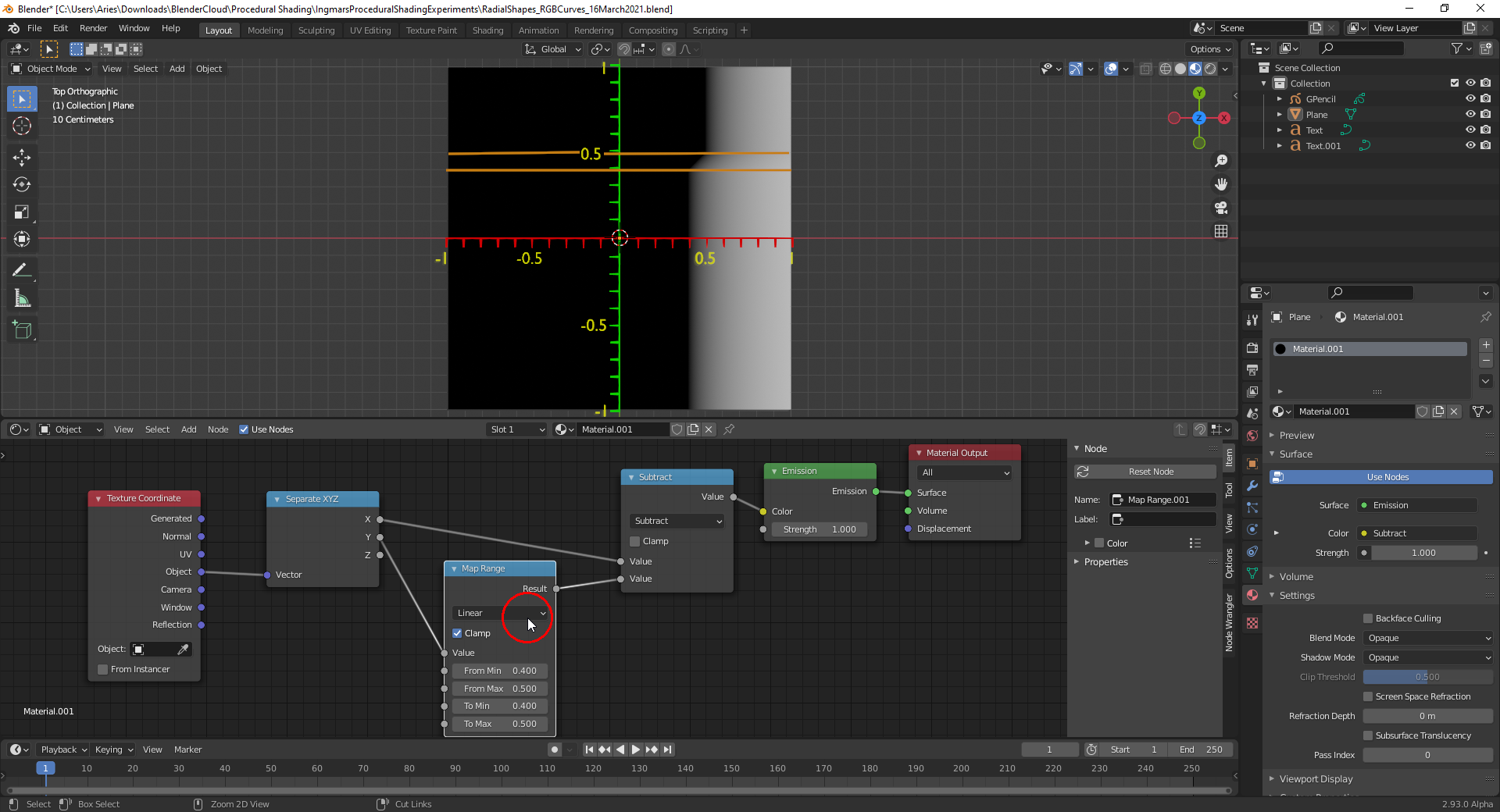
![]() dostovel Subtracting local Y from local X gives you a diagonal gradient:
dostovel Subtracting local Y from local X gives you a diagonal gradient:

If you now remap the local Y coordinate using "Clamp" the two values at the "To" interval limits are extended outside that interval into infinity so that we subtract a constant value from local X:
![]() spikeyxxx I remember Simon Thommes saying in one of his "Procedural Shading" videos that the advantage of a node tree is that you can move the nodes around until you get the desired result. So, he's sometimes also relying on the trial and error method😉.
spikeyxxx I remember Simon Thommes saying in one of his "Procedural Shading" videos that the advantage of a node tree is that you can move the nodes around until you get the desired result. So, he's sometimes also relying on the trial and error method😉.
![]() spikeyxxx I'm just reading about the "Mapping Node" and the order of transformations in the "Blender 2.93 Manual":
spikeyxxx I'm just reading about the "Mapping Node" and the order of transformations in the "Blender 2.93 Manual":
- Vector Type
The node applies the transformation differently depending on the semantic type of the input vector.
- Point
For this vector type, the node performs a straightforward transformation.
Transforming a texture coordinates is analogous to transforming a UV map. For instance, translating the texture coordinates along the positive X axis would result in the evaluated texture to move in the negative X axis, much like if one translated a UV map. Similarly, scaling the texture coordinates up would result in the evaluated texture to scale down. So transforming the texture coordinates would appear to have the opposite effect on the evaluated texture.
The order of transformation is: Scale –> Rotate –> Translate, which means:
Translation moves the input along the local rotation axis.
Rotation rotates the input around the origin of the space.
Scaling scales the input along the global axis.
- Texture
For this vector type, the node performs an inverse transformation.
Inverse transforming a texture coordinates would, as opposed to the Point type, transform the evaluated texture itself. For instance, translating the texture coordinates along the positive X axis would result in the evaluated texture to move in the positive X axis, as one would expected. Similarly, scaling the texture coordinates up would result in the evaluated texture to scale up, as one would expect.
The order of transformation is: Translate –> Rotate –> Scale, which means:
Translation moves the input along the global axis.
Rotation rotates the input around the translation vector.
Scaling scales the input along the local rotation axis.
I'm wondering what "global axis" and "local rotation axis" are meaning here and why for example "Scaling" in "Point" mode uses the "global axis" whereas in "Texture" mode it uses the "local rotation axis".
And what are the usecases for the "Normal" and "Vector" modes?
![]() spikeyxxx And yet another question: Do you know what the "round" function of the "Math Node" does with a value like 0.5? Does it round up or down?
spikeyxxx And yet another question: Do you know what the "round" function of the "Math Node" does with a value like 0.5? Does it round up or down?
The order of transformation is: Scale –> Rotate –> Translate, which means:
Translation moves the input along the local rotation axis.
Rotation rotates the input around the origin of the space.
Scaling scales the input along the global axis.
Just read those 3 lines from bottom to top (in the order they are calculated) then it makes more sense ( I hope...otherwise just ask again and I will try and explain ti better).
And what are the usecases for the "Normal" and "Vector" modes?
I don't know, have never used them...apart from behaving different, all 4 modes get the job done so I just stick to Point, so as not to get confused...there are situations where you want a different order, but then you can use two Mapping Nodes after one another (as explained before in Kent's stylized forest course). Remember that Point is the cheapest version of the Mapping Node; all others must first convert by multiplying with a Matrix...
So, he's sometimes also relying on the trial and error method
Well that is sometimes easier than figuring out the exact order of the Nodes....you can always figure it out afterwards, when you have found the correct way, why it has to be like that 😉