Get it? Math Lab.... sounds like Me.... Lab?.... No? ok
So ![]() spikeyxxx you're like a super mathematician, I'm doing the Blender Cloud Procedural Shading course and it is super heavy dense in tough, difficult and impossible things and worst of all there's like a lot of math involved. I wanted to use this to bother you a lot and ask you math questions when it comes to procedural shading.
spikeyxxx you're like a super mathematician, I'm doing the Blender Cloud Procedural Shading course and it is super heavy dense in tough, difficult and impossible things and worst of all there's like a lot of math involved. I wanted to use this to bother you a lot and ask you math questions when it comes to procedural shading.
The course is good but Simon goes way too fast and doesn't get into the really basics and assumes you know what happens mathematically under the hood.
*WARNING, HERE BE MATH*
![]() spikeyxxx I'm wondering what Simon Thommes means when saying that the values from the "Color" output of the "Noise" texture node are centered around 0.5. And what's so special about the "Linear Light" blend mode of the "MixRGB" node that it can be used for mixing in that "Color Noise" into your "Texture Coordinates"?
spikeyxxx I'm wondering what Simon Thommes means when saying that the values from the "Color" output of the "Noise" texture node are centered around 0.5. And what's so special about the "Linear Light" blend mode of the "MixRGB" node that it can be used for mixing in that "Color Noise" into your "Texture Coordinates"?
![]() duerer this is what he means with Noise output is centered around 0.5 (just think of this as one of the three RGB channels):
duerer this is what he means with Noise output is centered around 0.5 (just think of this as one of the three RGB channels):

Now Linear Light does not change 0.5 as can be seen here:
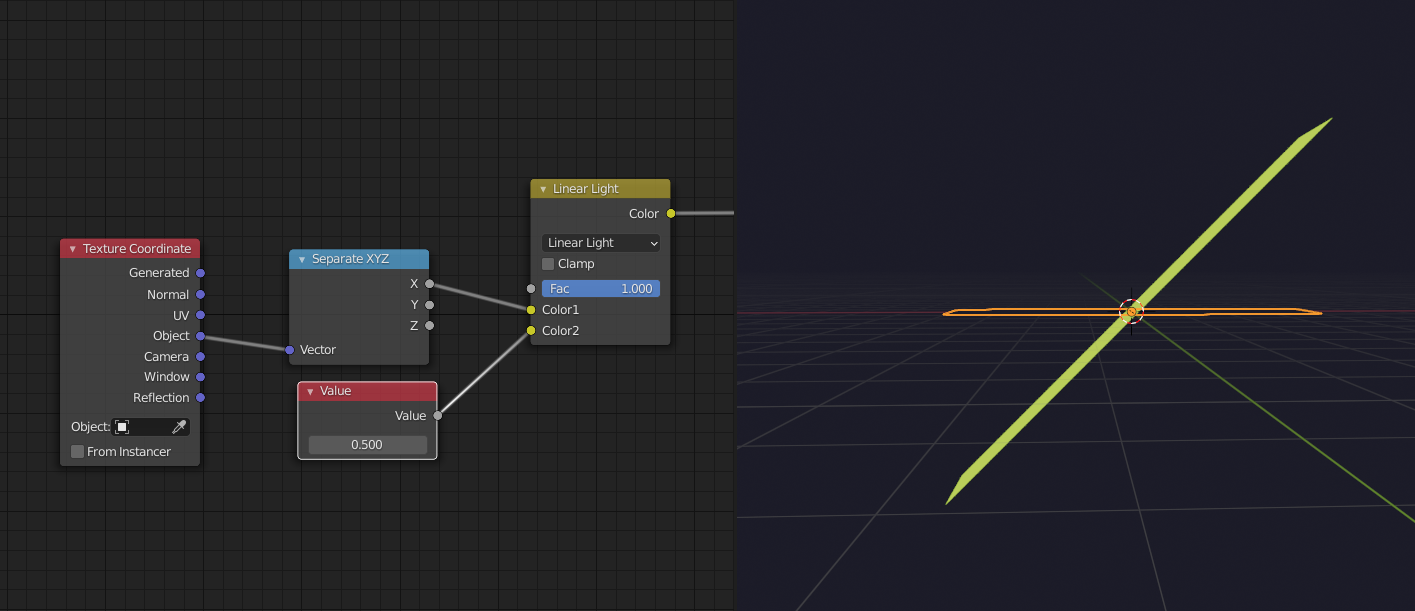
This is the same as directly plugging the X in the Displacement Height. So if you pug in a Noise Texture in Color2, in stead of this Value Node, it will preserve the average of the Noise. Mathematically Linear Light does this:
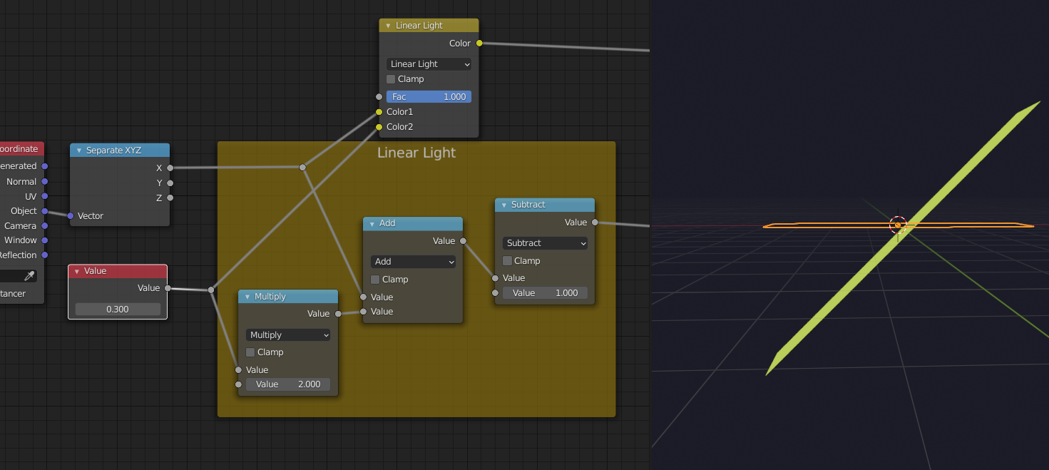
It doubles the strength of the Noise, but doesn't 'shift' the original...
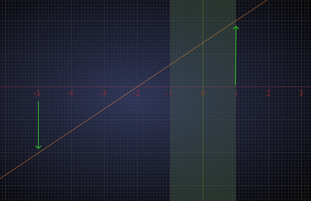
in the above picture: 3 becomes 1 and 1 becomes 2 (see the green arrows).
I can see the 1 becoming a 2 From Min To Min is set to 1 and 2
But 3 becomes 1? or 3 becomes 0? It is set to From Max 3/To Max 0
I think I kind of get what the map rage is doing. This node should be renamed to Remap Range Node. I yet have to see what's the advantage of doing this.
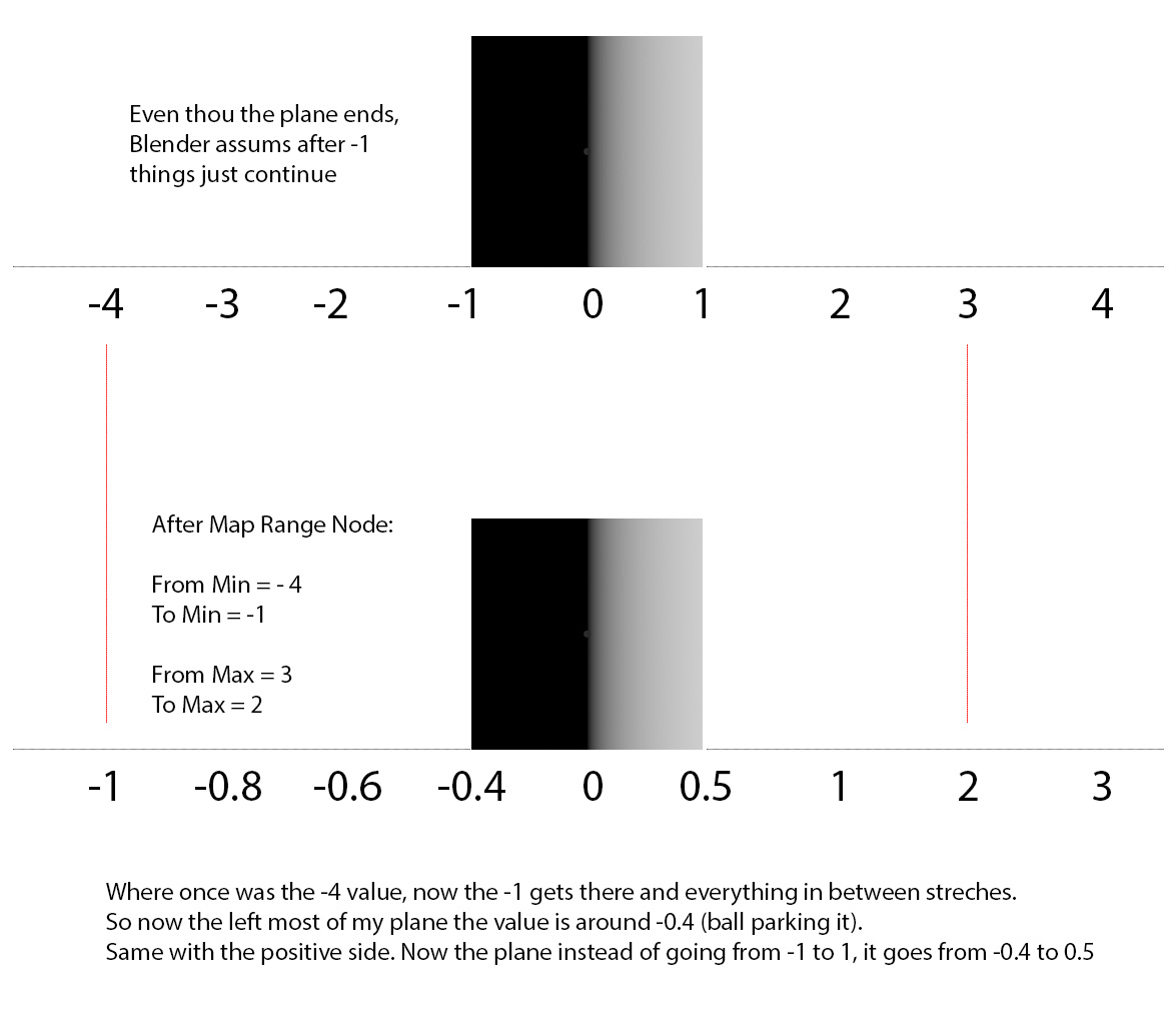
I have a question, because I still can't see the functionality pictured in my head. If I have a plane, I separate the X, now I have a gradient in X that goes from -1 to 1 which seems to be the default, then I plug a Map Range, From Min -1/To Min 1 and From Max 1/To Max 2...…. now my plane will be entirely white and the left most value in the start of the plane will be 1, and the right most value at the end of the plane will be 2, my question is.... what if I had said From Min -5/To Min -2? There were no such values in the plane to begin with, how does the node interpret that?
You're absolutely right, Omar, I wasn#t paying attention: 3 becomes 0 as can be seen in the Map Range and in the picture ;)
When you set it From Min -5 To Min -2, then the Map Range Node sets Where X = -5 to -2 and with From Min 1 To Max 2, it sets where X = 1 to 2...and the interpolates linearly (draws an imaginary line) between those values. So where X = -1 (the left side of your Plane) it would get the value 0.4 ...if you would extend the Plane, it would become 0 at X = -2.
![]() spikeyxxx So, "Linear Light keeps 0.5 in place" means that any RGB value from the "Color" output of the "Noise" texture node won't have any influence on the coordinates since it's multiplied by two which equals 1 that is subtracted at the end of the orange frame above. The "Add" node brings in the texture coordinates.
spikeyxxx So, "Linear Light keeps 0.5 in place" means that any RGB value from the "Color" output of the "Noise" texture node won't have any influence on the coordinates since it's multiplied by two which equals 1 that is subtracted at the end of the orange frame above. The "Add" node brings in the texture coordinates.
Simon Thommes, if I remember it correctly, uses a "Vector Math" node in order to subtract 0.5 for all the coordinates from the "Color" output of the "Noise" texture node and scale this up with a "Vector Math" node in "Scale" mode in order to avoid any coordinate shifting by 0.5. In the last step noise and texture coordinates are added together.
So, in other words, we have to take care that the "Midlevel" values of the "Object" texture coordinates and the "Color" output of the "Noise" texture node get synchronized.
![]() spikeyxxx I think, a visualization would help. The mapping of the end values is clear but even with a linear interpolation I can't simply see where a value in between the two "From" interval limits gets mapped to in the target interval. I suppose that it works with "Linear" interpolation by calculating a percentage in the "From" interval and doing it similarly in the target interval. But what if I change the interpolation type 🤪?!
spikeyxxx I think, a visualization would help. The mapping of the end values is clear but even with a linear interpolation I can't simply see where a value in between the two "From" interval limits gets mapped to in the target interval. I suppose that it works with "Linear" interpolation by calculating a percentage in the "From" interval and doing it similarly in the target interval. But what if I change the interpolation type 🤪?!
![]() spikeyxxx I've just seen the Simon Thommes uses the "Factor" output of the "Noise" texture node with a "Color Ramp" afterwards and plugs the ramp's output into the "To Min" input of a "Map Range" node 😱🤪😵!!!
spikeyxxx I've just seen the Simon Thommes uses the "Factor" output of the "Noise" texture node with a "Color Ramp" afterwards and plugs the ramp's output into the "To Min" input of a "Map Range" node 😱🤪😵!!!
So, "Linear Light keeps 0.5 in place" means that any RGB value from the "Color" output of the "Noise" texture node won't have any influence on the coordinates
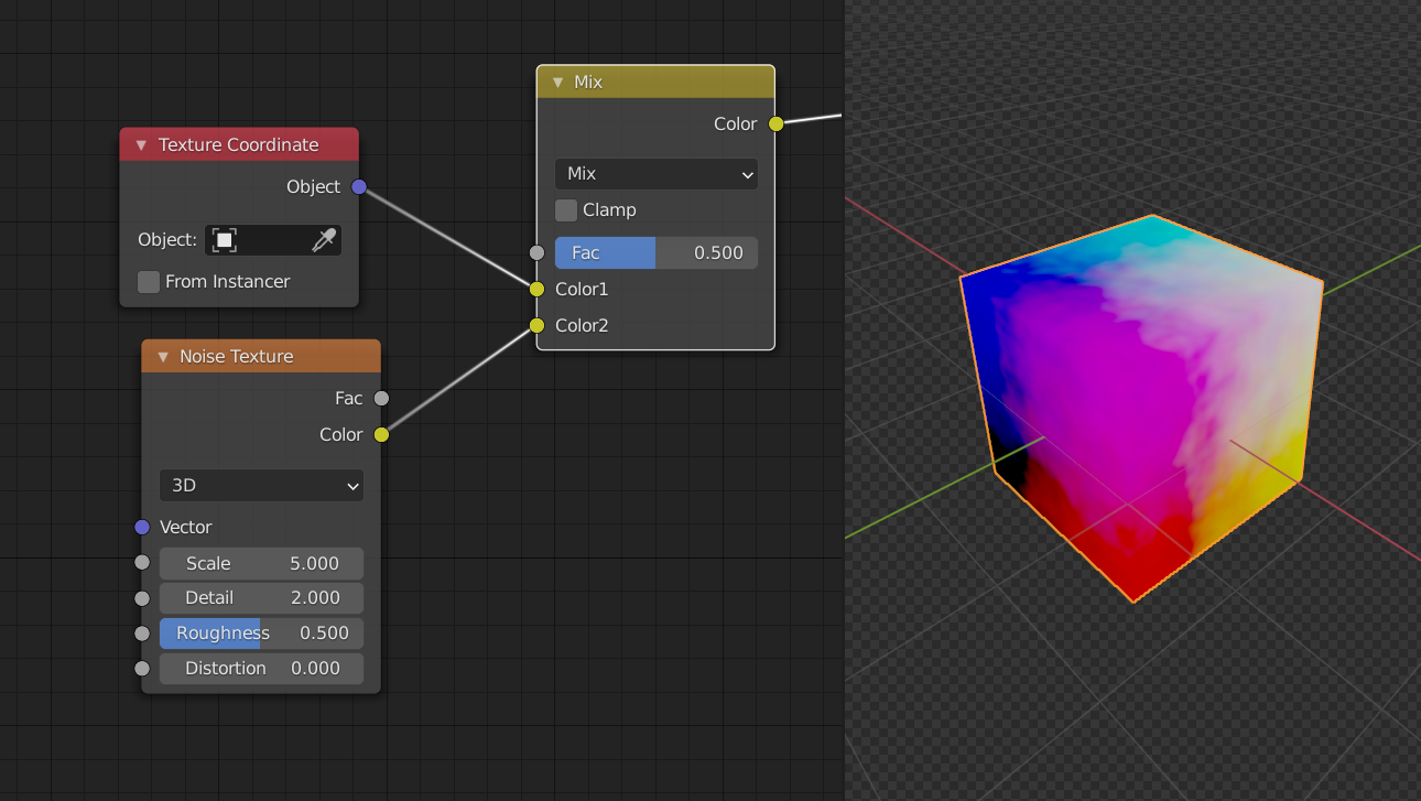
No no no, you plug the output of the Noise Texture into the bottom socket of the MixRGB (set to Linear Light) and almost every RGB value of the Noise will have influence on the top input and usually that are coordinates:
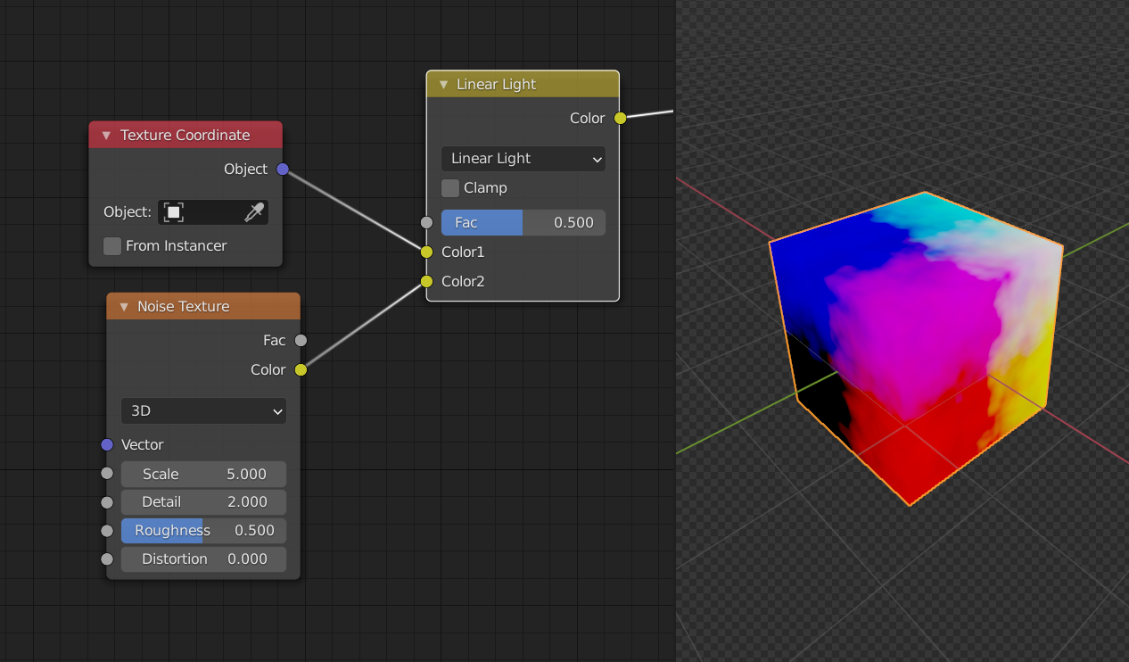
Compared to Mix:
So, in other words, we have to take care that the "Midlevel" values of the "Object" texture coordinates and the "Color" output of the "Noise" texture node get synchronized.
No, we take care that the 'midlevel' or the Noise Texture doesn't change the coordinates.
And yes, you can do that with (Vector) Math nodes as well, but to use one MixRGB node is easier and also has a handy influence slider built in.
Man, I should really work on my calculations:
That does not look like 0.4 at X = -1
Don't know what the other interpolations do exactly...
Is it like this Spikey?
In my head I picture it like a bully that goes to the number it's order to and punches it and takes it place and all the other bad guys that follow him in an accordion motion move accordingly. Right?
![]() spikeyxxx I just thought about your node setup from above:
spikeyxxx I just thought about your node setup from above:
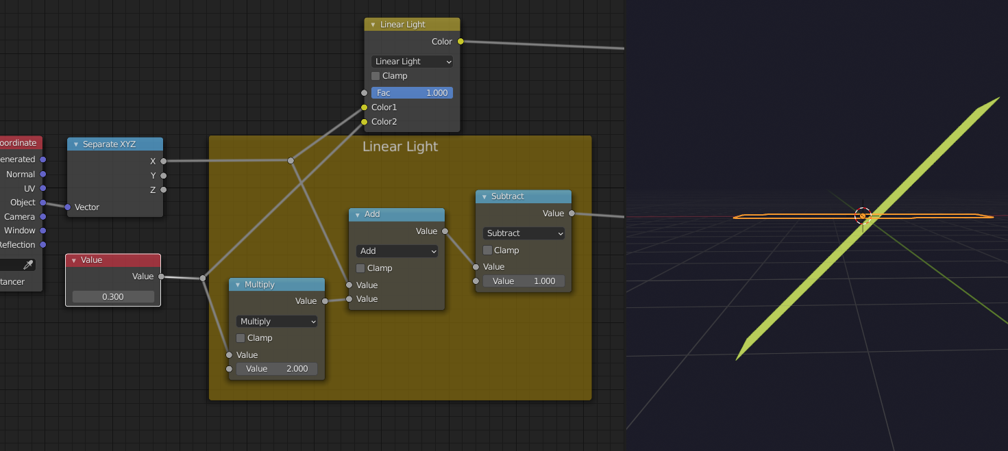
If you set the "Value" in the bottom left corner to 0.5, it gets multiplied by 2 which equals 1. This result is added to the X coordinate of the "Object Coordinates". The subtraction of 1 at the end neutralizes the 1 from the beginning which was the result of a calculation with 0.5 as input. So, the input of 0.5 doesn't change the "X Object Coordinate".
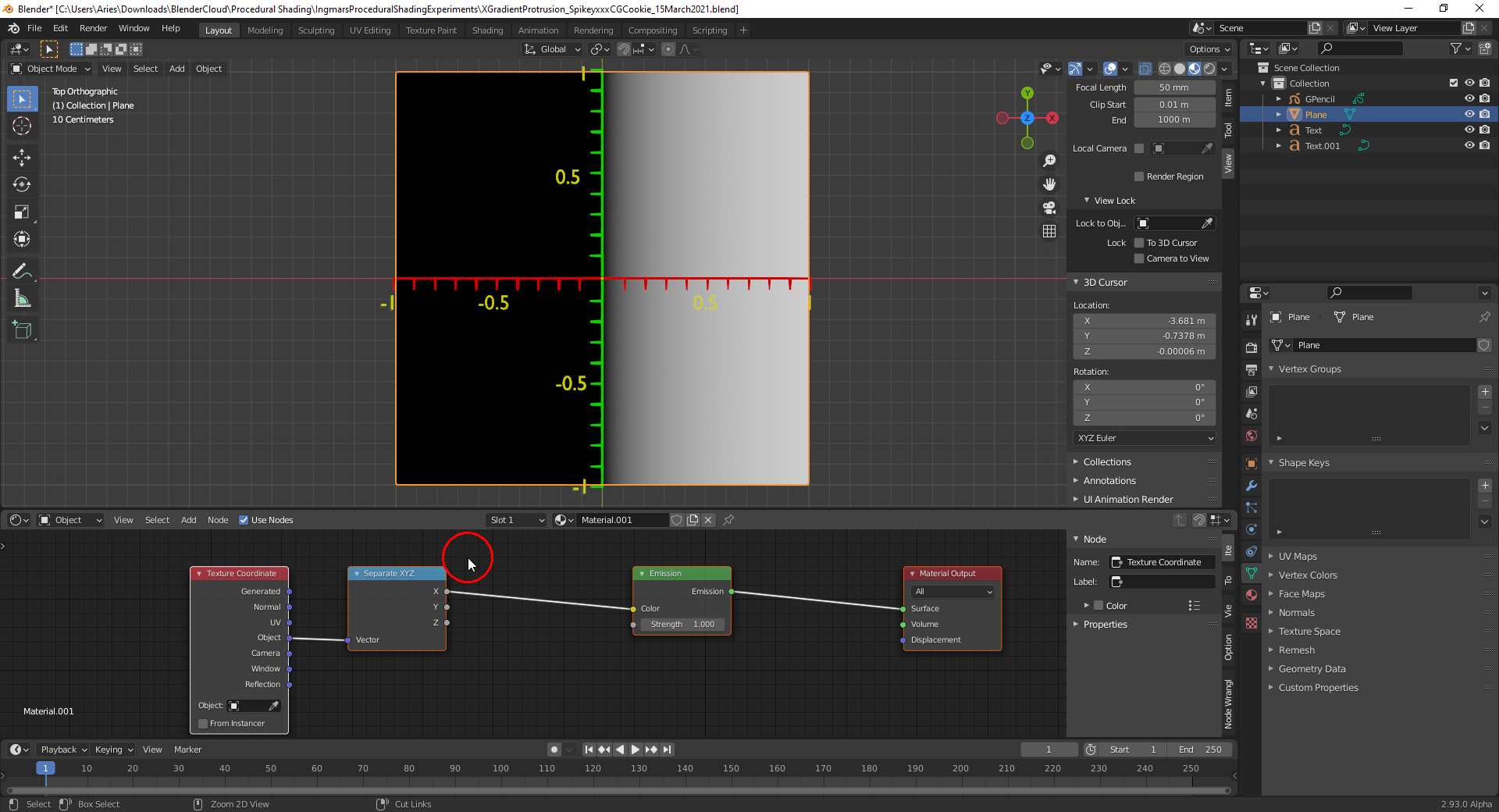
First step when trying to explain this:
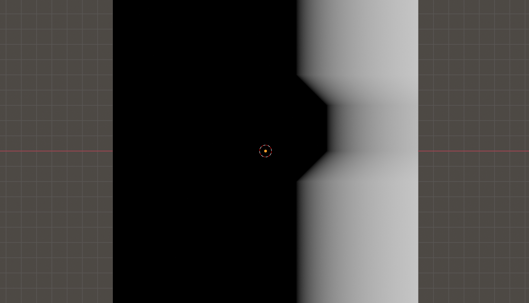
I start with a gradient in local X direction (note: the local axes of the plane are aligned with the global axes for demonstration purposes).
I want the black protrusion happen at the top between 0.5 and 0.4. So I create a gradient in local Y that only changes in that area. This can be done with a "Map Range" node where I map that interval onto itself and use "Clamp" so that the values at both extremes of that interval are copied outside the interval (here demonstrated with a "Color Ramp"):
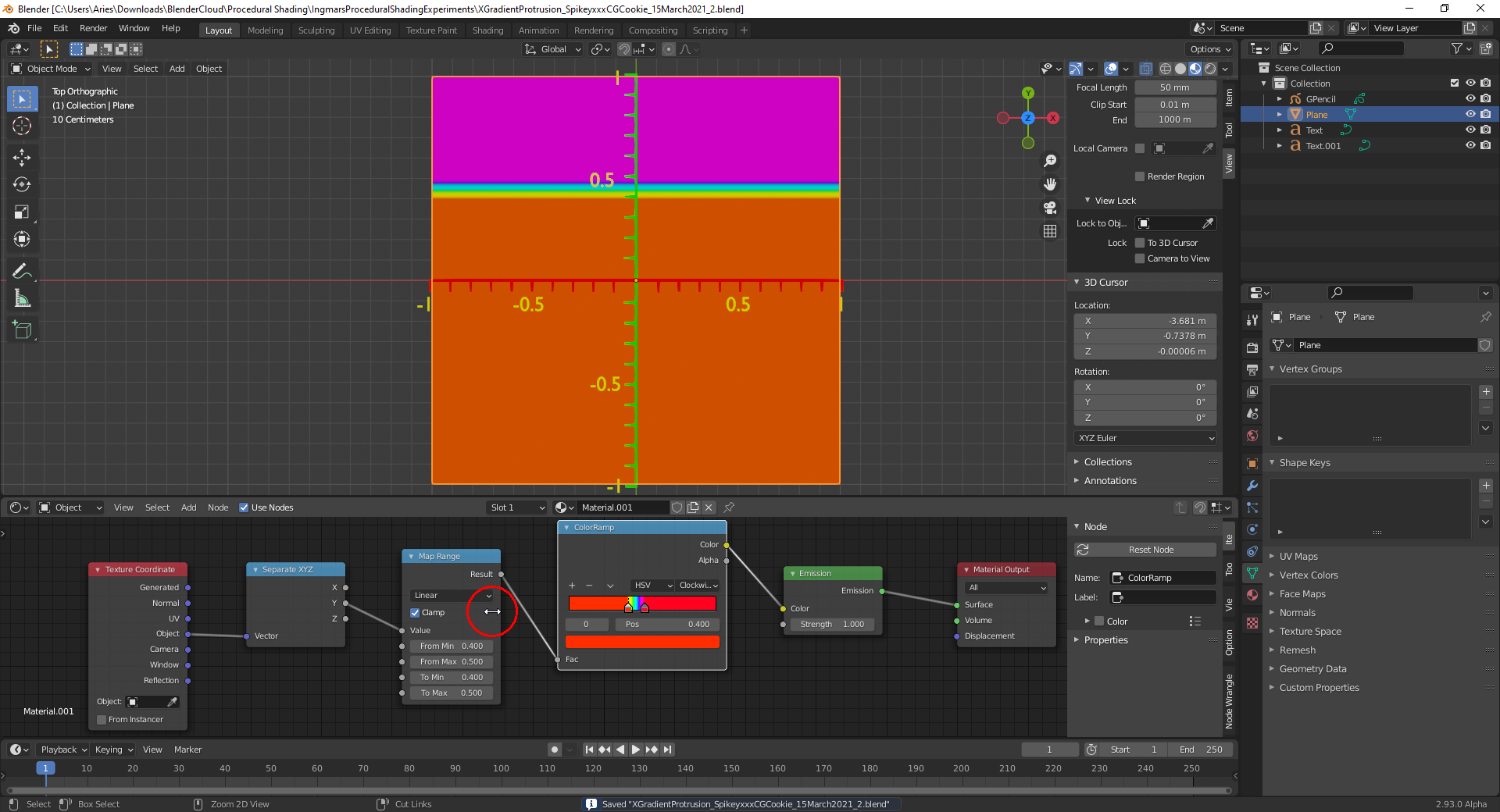
End of part 1
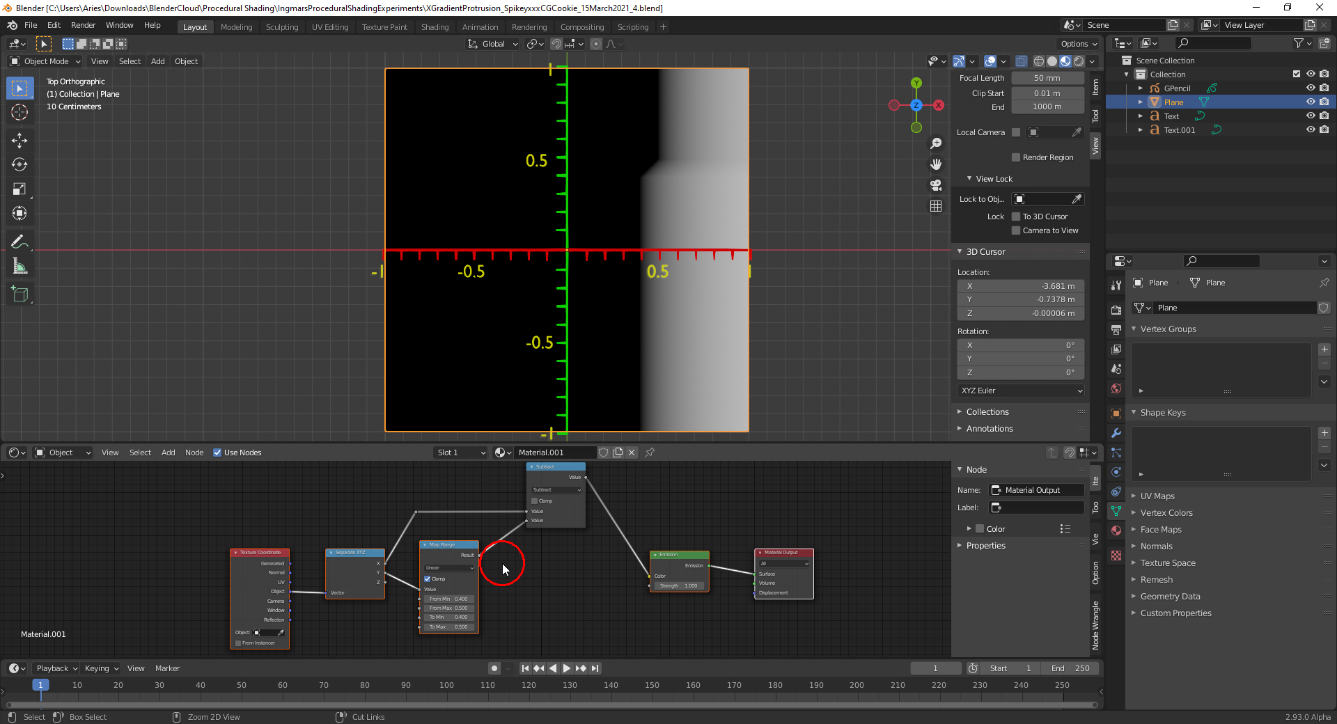
For achieving a change in the local X axis gradient between local 0.4 and 0.5, I now need to subtract the first local Y axis gradient from the local X axis gradient:
I can mirror the direction of the protrusion by swapping "To Min" and "To Max" in the "Map Range Node" for the local Y axis gradient:
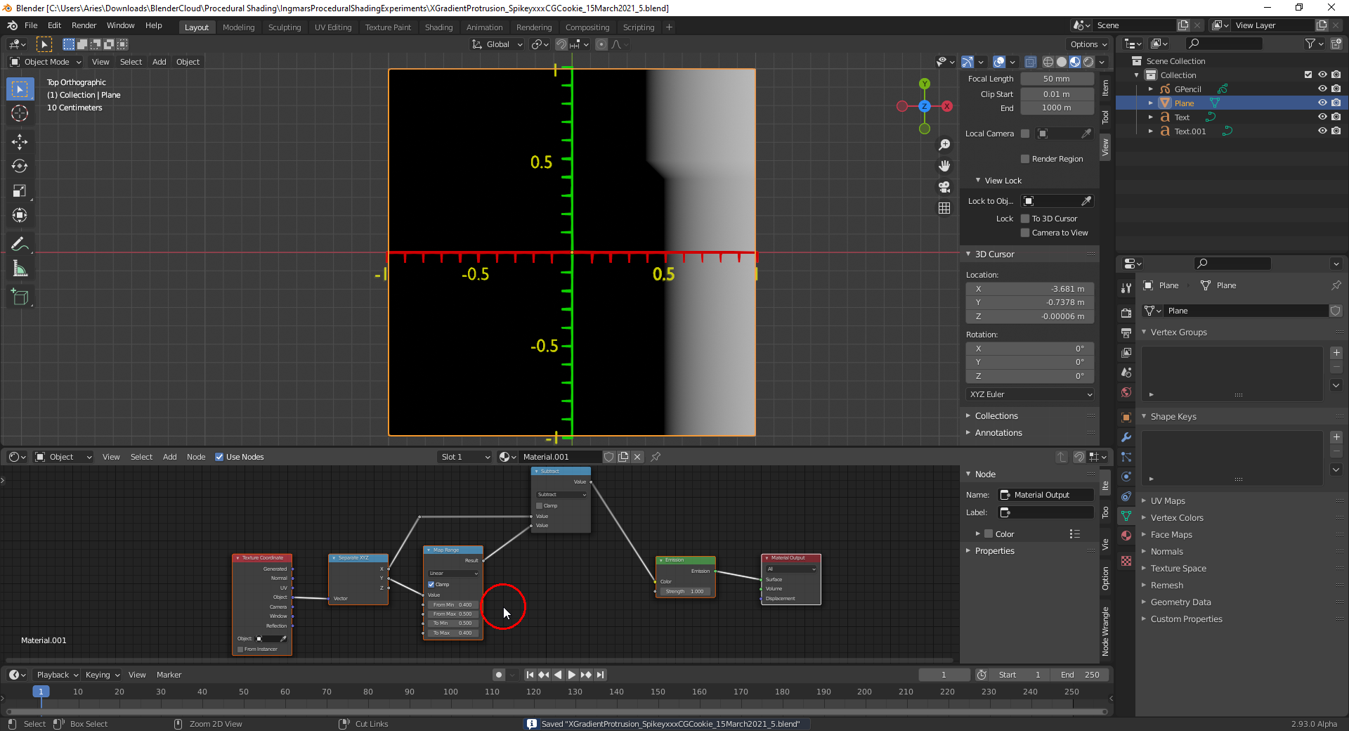
End of part 2

Excellent, thanks Spikey.
Now, how did you calculate that those are the exactly values? I would like to understand that if it's not too complicated. And if I do just that and make a render, will the color picker pin that value at -0.25 in the left most pixel and 0.666 at the right most pixel?
EDIT: Ok no, I just tried making the render but if you right click to sample the pixel, it normalizes the values from 0 to 1, it crunches everything.