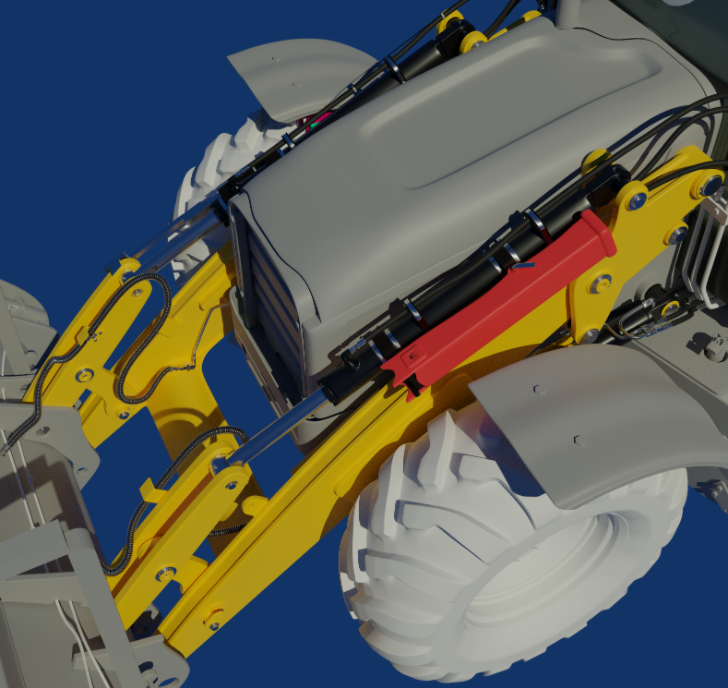
Progress, Questions, and Comments for Loader Arms and Interior Chair on the DOG 434E Backhoe Loader posted here:
I am not sure if I understnd the problem correctly, but I think I agree with Parker ppfbourassa , imagine this in an extreme situation:
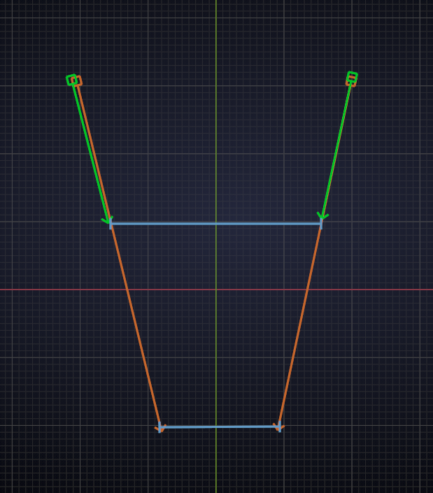
When the green hydraulic cylinders are not parallel and extend into the red arrows, what they are connected to (blue) would be squashed..
I'd say they must be parallel...
Like I said, I am not sure if I understand what's going on...
Just found this front view
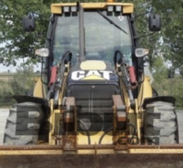
I agree the arms and pistons need to be parallel to function correctly.
If you look close, zoom to the top arm from the piston to the bucket, to me it looks like a thin piece on one side of the piston.
had another look at other images and they all show as you have it. Maybe as suggested by ppfbourassa the top of the piston slightly closer to the engine, so they are parallel but maybe not exactly above the lower arm. It’s so difficult to see, need an up close and personal look.
@adrian2301 yeah that is a different loader arm design, the 430F that I got pictures of uses that. The side pieces mount on both sides for that design and there are two pieces where my "one" red piece would be.
Here's another viewpoint where I talked about it with things shifting to be centered like people are suggesting and why that obviously is not going to work. I can try to shift stuff over like ppfbourassa Parker has suggested but man all of the reference that I see these top yellow pieces that hug the red piece are really close together. So I am at a loss of what to do unless I widen the loader arms like in this photo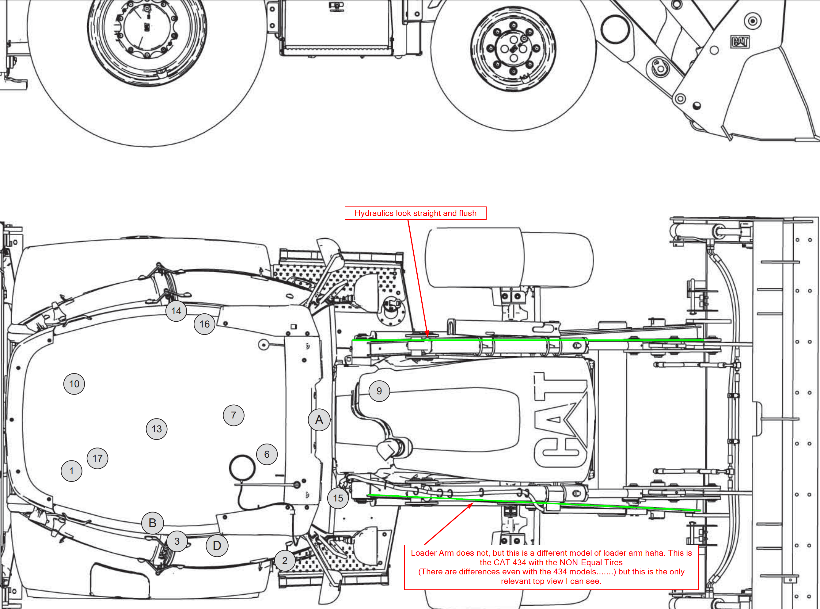
Crap.......I found the issue. The loader arms spread out just like in the picture above...........dun dun dun! I found the loader arm design we are using and it is doing the same thing. I can't post the picture though. We already have this picture in our forum so I don't feel bad posting a higher quality one even though it is not exactly our model. Took a look around in my special access and yup. I did it wrong. That's a bummer. I get to spread that loader arm out now. I'll see if I can fix it tonight and resubmit.
I'll really try to get this working and resubmitted by tonight or tomorrow so that you have something to work with Parker. You've waited long enough for me to mull it over haha. We need to connect that bucket so the magic can start happening.
This is why I kept those parts flexible so far. It looks like my "fins" are still straight, so I'm not exactly sure how that junction will end up working.
ppfbourassa. I have submitted the revision on the group sheet. As long as Kent doesn't see any issues. I plan on leaving the connection points where they are. The bottom piece connects to 1 fin and the top to a different fin, just FYI. Reference pics here in this forum from Adrian for more info.
My first draft at the hydraulic lines from one assembly to another. I'll work on the piston hydraulics tomorrow hopefully.
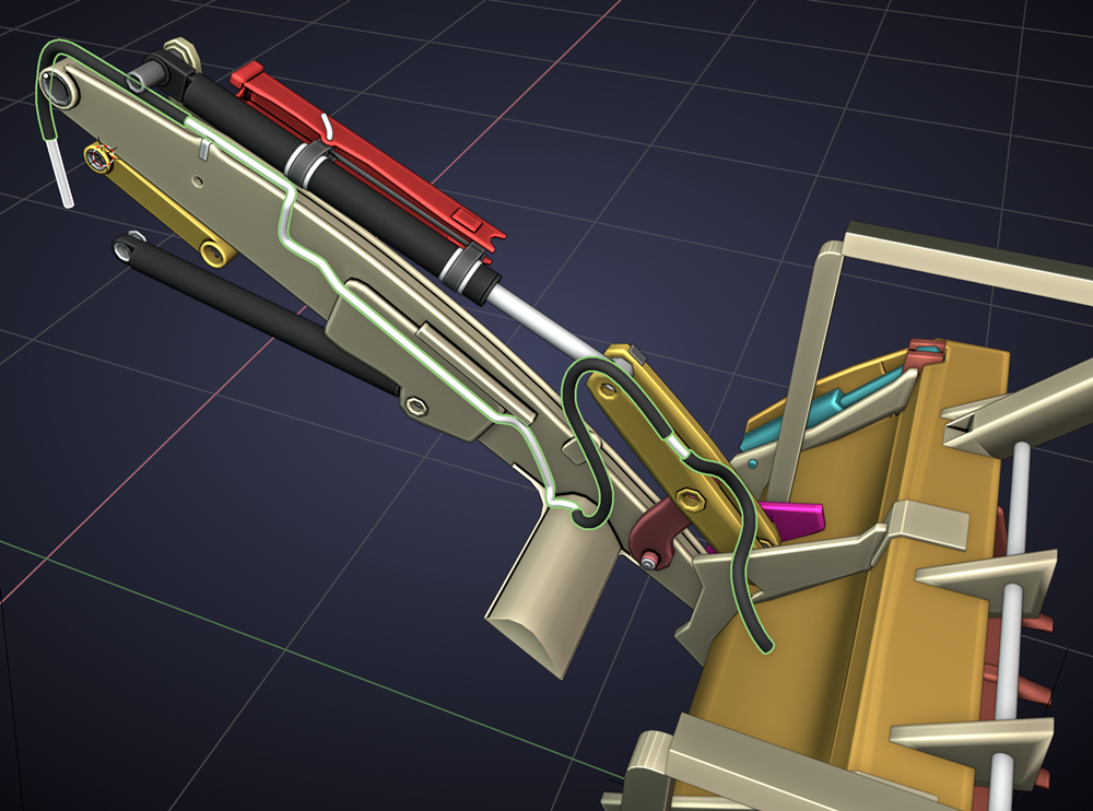
@adrian2301 There is a tank near the rear of the loader arms Between the aft pivot points that sits on the chassis and below an overhead support. The tank is vertical and looks similar to a fat radiator without the fins haha. That holds all of the hydraulic oil to my knowledge. Have you seen it along with the other hydraulic connection points for the front?
Do you mean this one:
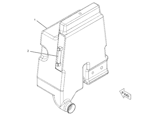 This I found is the tank for the hydraulic fluid and supplies all hydraulics. It sit above the gearbox. The lines from here go to the control valves which are attached to the chassis, then on to the individual pistons. I may go as far as the control valve, and then reassess and decide if it's really worth going to the tank. With the gearbox installed this will probably not be seen.
Yup that is the one I believe. I agree it is probably never going to be seen.
Looks great ![]() blanchsb. Funny how satisfying a well-formed hydraulic line can be to my inner 3D modeler.
blanchsb. Funny how satisfying a well-formed hydraulic line can be to my inner 3D modeler.
Yeah they are extremely satisfying, perhaps because you see results more quickly?
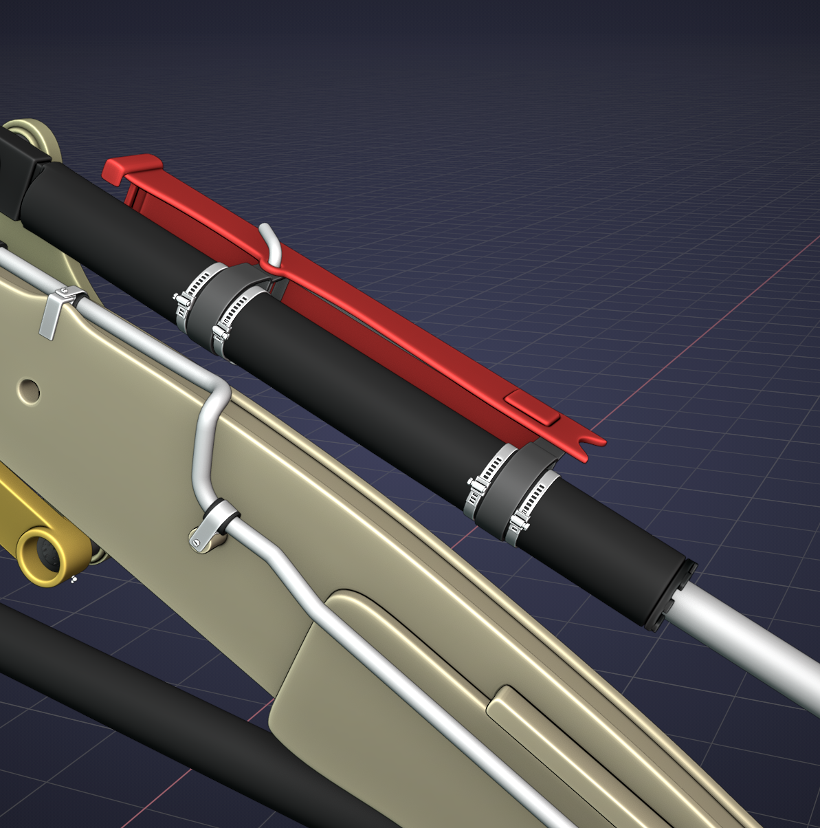
Was able to work some of the finer details today on the upper hydraulic supports and added some jubilee clips to the metal bands. I left the threads on the screws off, but I think it looks passable....... except I made them the wrong direction against the holes. I'll have to correct that tomorrow haha.
I also added the zerk fittings to the loader arms:
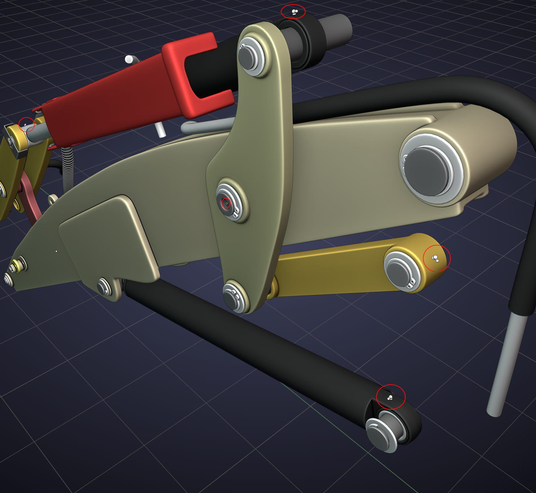
They should be to scale but man do they look small compared to everything else.
I completely redesigned the jubilee clip band using a template bezier circle and two base thin band meshes. One piece represented the band with the tightening cut-out slits and the other represented a solid band.
I assigned them both to the bezier circle to start with.
Once I got it all into position around the piston I duplicated a small section of the bezier circle and separated it to a separate piece. Then I cut a small portion of that duplication area out of the original bezier circle just below the tightening screw.
Then I assigned the base mesh band with slits to the smaller portion of the separated duplicate.
So two pieces fitting into 1 per-se. I haven't mated them up yet but I thought I would share my thought process. This actually took me all night to think about haha.
Hopefully that makes sense. Maybe ![]() spikeyxxx could recommend a better process but I think I was being clever this time around.
spikeyxxx could recommend a better process but I think I was being clever this time around.
I'll make the individual jubilee clips a little more unique tomorrow but that is an easy task of just moving the small bezier curve around a little. It would be nice to know if there was a way to join the two pieces together easily. I may just apply the mods once I am happy with it and do a quick merge since it is only one section that needs to be mated from the two band base meshes.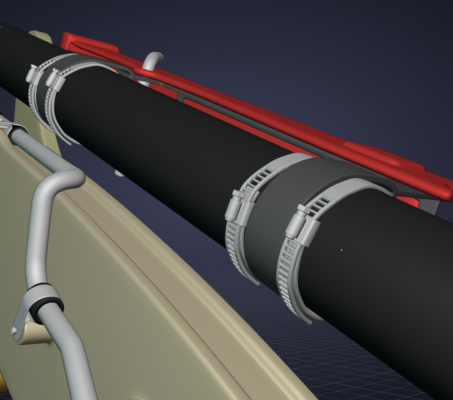
Looks great Shawn! Good technique as well.
I'd do it almost the same, but with only one mesh..
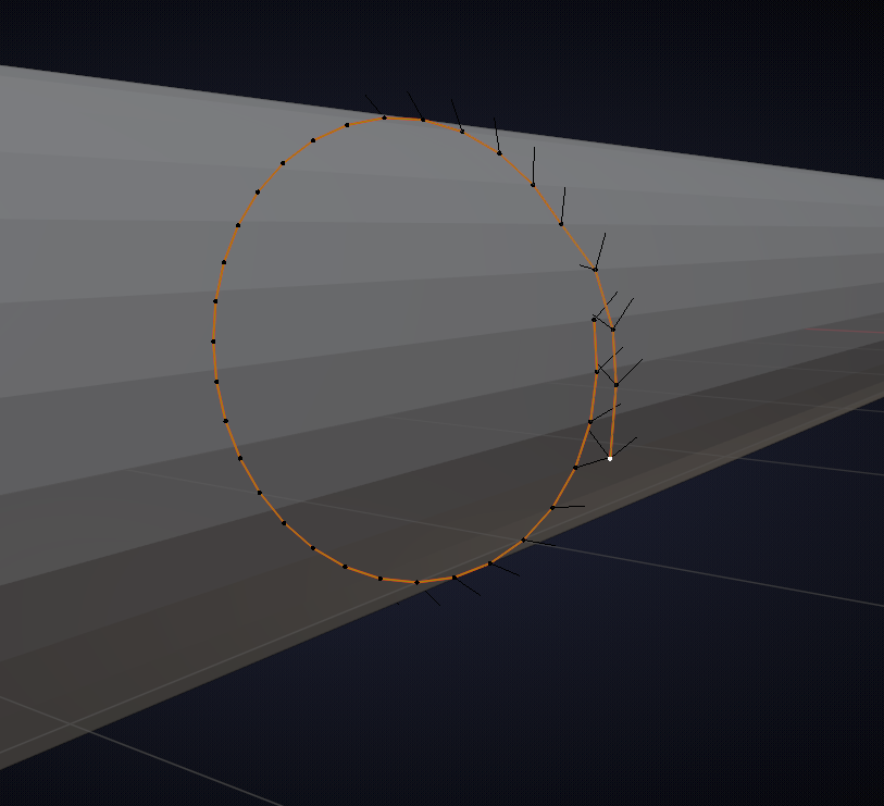
Make a loop cut on the 'cylinder' and slide it into place. P > Separate by Selection. Take that new piece in Edit Mode and delete one vertex (where overlapping should occur). Convert the Mesh to a Curve and extrude the overlapping end:
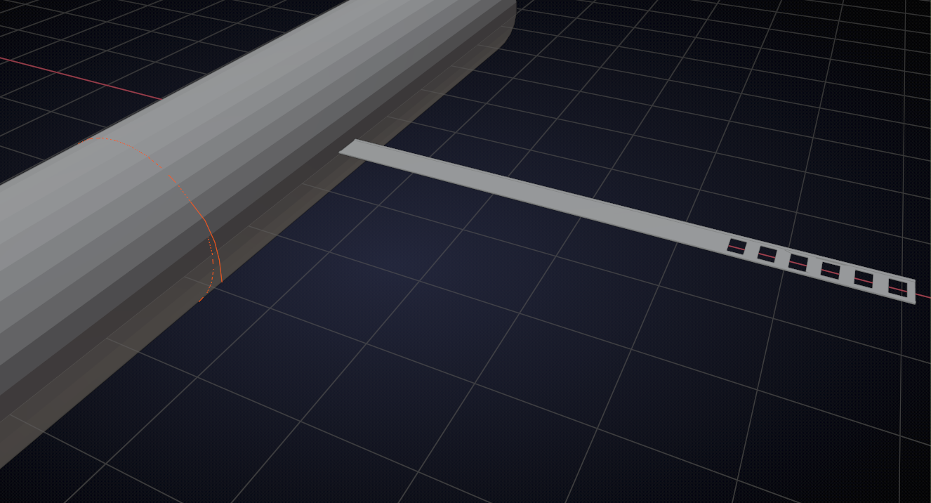
Then you can model the band straight (as one piece and a bit better than I did here):
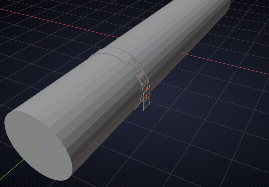
and add a Curve Modifier:
Oh man, I knew you would have a better way. That is really cool. Yup I am going to have to do that instead. Rev 3 coming up over the weekend.