This is the thread for my progress on the Backhoe Collaboration.
Ask me questions, give suggestions and post some images that may help my progress.
Thanks
Just looking over the Fenders and feel they are 99.9% complete. Looking at the detailing on the front fenders as talked about in the live stream,
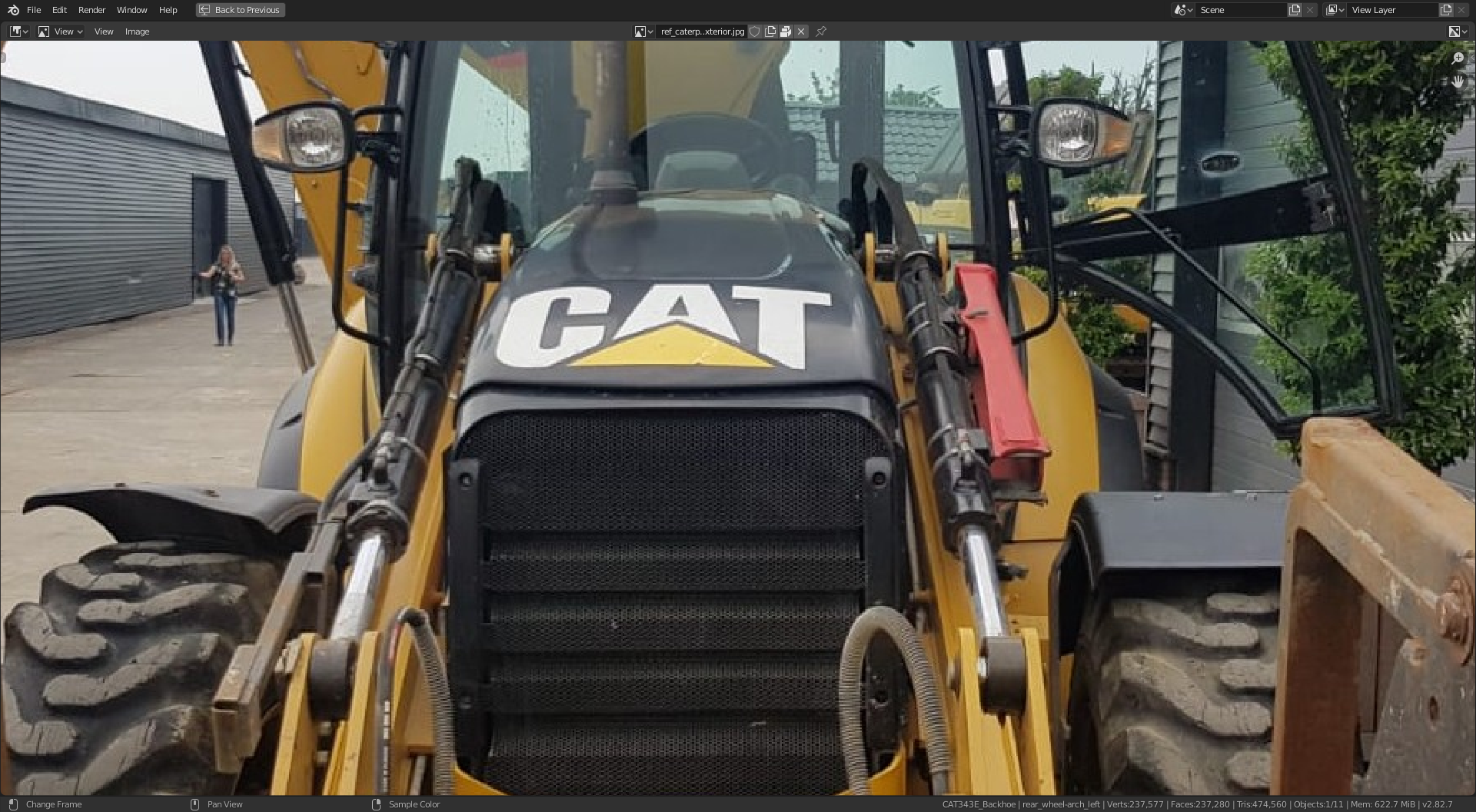
The fender on the right, as we look at this angle, looks like it maybe new, fitted for this photo op. The left looks older and probably the original for this model of 434E. So I will stick with what I see as the original. The new is flat but has the edge detail all round, including across the top. The original has the curvaceous look, but not the detail across the top.
The other point on the rear fenders is the solidify mod,
This is with default, only rim unchecked.
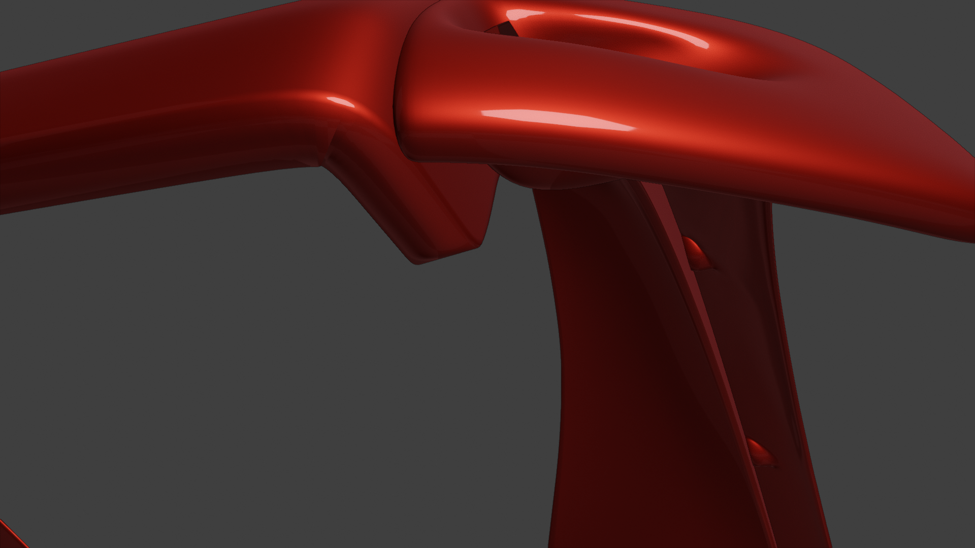
And this with, only rim checked.
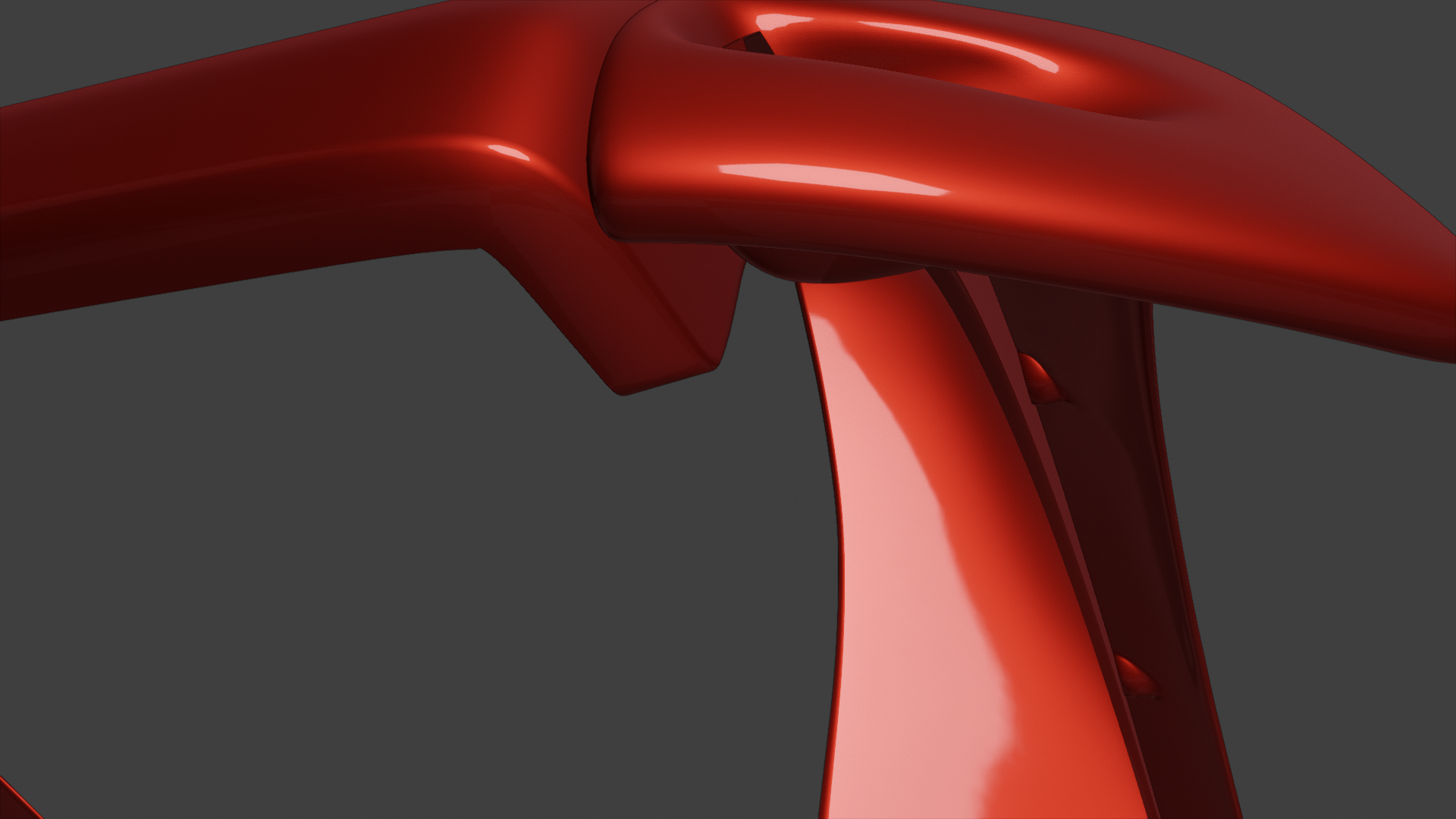
With only rim checked, they corner in particular is much cleaner, the question is do I go for an illusion of thickness or actual thickness??
And one more question for @theluthier , would you rather we upload our file with just our parts but with the naming conventions as previously discussed, or as the master but renamed?? I am finding it easier and faster to have a separate file and link in any other parts for referencing.
I really like it @adrian2301. We need to get together to divvy up the remaining engine parts, unless you are lone-starring it.
Also, I have been meaning to ask if there is an end-cap feature to add the crimped fittings onto the end of hoses that use bezier curves? I wonder if it is applicable for some of these lines?
Thanks ![]() blanchsb , I watched the live stream again and had a little smile when I listened to @theluthier 's remarks about the engine, and I admit, I watched that bit twice more.
blanchsb , I watched the live stream again and had a little smile when I listened to @theluthier 's remarks about the engine, and I admit, I watched that bit twice more.
Not too much left on the engine it's self, the gearbox was next, but that is probably just one big piece, just a matter of the shape.
![]() jakeblended is on the spaghetti around the swing frame, as @theluthier said , I'm not so sure that part I linked in the stream will be seen, is it worth the effort. I could probably model it in about an hour or so. Jake has a bigger part right behind the swing frame, where all Kent's and his as well as my 2 lines on the stabilizer all attach, don't think it's worth going further than that.
jakeblended is on the spaghetti around the swing frame, as @theluthier said , I'm not so sure that part I linked in the stream will be seen, is it worth the effort. I could probably model it in about an hour or so. Jake has a bigger part right behind the swing frame, where all Kent's and his as well as my 2 lines on the stabilizer all attach, don't think it's worth going further than that.
What about your end ![]() blanchsb , do you know how far your going with the lines on your loader arms??
blanchsb , do you know how far your going with the lines on your loader arms??
By the way ![]() dostovel I have two fuel lines to go into the fuel tank. Do you want to attach them to the spacer thing I got as far as or do you want me to continue all the way to the tank??? See Below..... Also your parts just need moving forward a little bit on both sides as there intersecting the chassis. I lined the chassis up with the axles and engine enclosure, if you don't mind.
dostovel I have two fuel lines to go into the fuel tank. Do you want to attach them to the spacer thing I got as far as or do you want me to continue all the way to the tank??? See Below..... Also your parts just need moving forward a little bit on both sides as there intersecting the chassis. I lined the chassis up with the axles and engine enclosure, if you don't mind.
Do you mean an end cap feature like on the array modifier??
I was thinking the same and did look at the settings , but didn't find anything.
The best way I found to get an end piece where I want it or the hose to the centre of the fitting is to place the 3D cursor in the centre of that piece and snap the last handle of the curve to the 3D cursor.
Maybe ![]() dostovel will know if that's possible.
dostovel will know if that's possible.
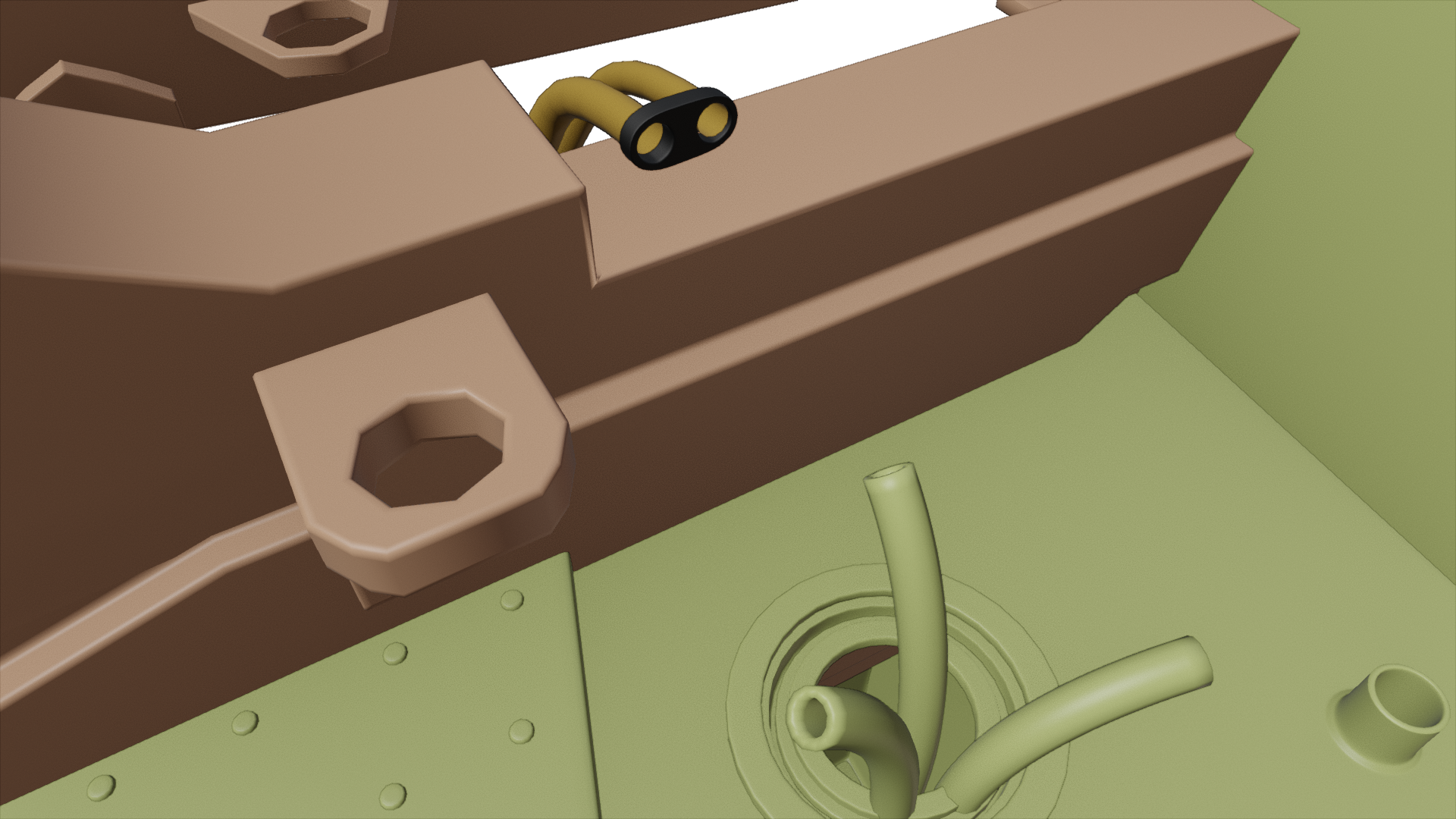
No one has mentioned who will be picking up the hydraulic lines that lead to the loader arms from the chassis. I can do some research and work that though. I might as well send the lines all the way over to Parker since they don't really interact with anyone else. I'll take a look into that this weekend hopefully.
![]() blanchsb I will do these lines 👇as they are actually attached to the chassis. these are the metal ones and then if you take the rubber hoses from there. I haven't looked yet but I assume this would be the same on the otherside.
blanchsb I will do these lines 👇as they are actually attached to the chassis. these are the metal ones and then if you take the rubber hoses from there. I haven't looked yet but I assume this would be the same on the otherside.
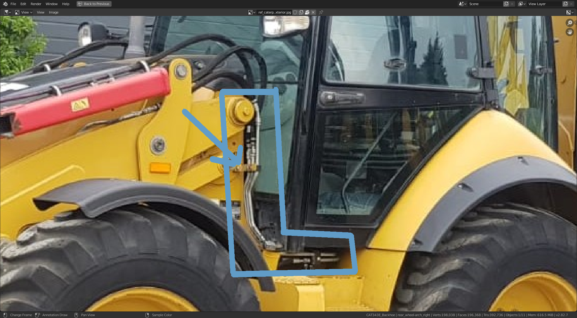
We could have one file for the hydraulics. If I create a file with the chassis, loader arms and bucket linked in, model these lines, and then I will pass the file to you. Then you do your lines, then pass it on to ppfbourassa for him to finish off. That way we can keep them all aligned correctly. What do you think??
Yeah I like that idea. I'll work on other fittings and routings until then. Let me know when you have your side ready and I'll in turn give my stuff to pfbourassa.
Beautifully updated pipe work @adrian2301! Clean and optimal 👌
I watched that bit twice more.
Well deserved! Seeing someone go above and beyond is contagious in a project like this ✊
![]() jakeblended I've finished placing the 8 hydraulic lines from the swing frame to the digging arm. I can throw the file your way whenever you need it. It will probably be best to cut the lines off cleanly with fittings where my lines are come out on one side and yours come out the other (clean separation of work). Just lemme know!
jakeblended I've finished placing the 8 hydraulic lines from the swing frame to the digging arm. I can throw the file your way whenever you need it. It will probably be best to cut the lines off cleanly with fittings where my lines are come out on one side and yours come out the other (clean separation of work). Just lemme know!
Started running some hydraulic lines:
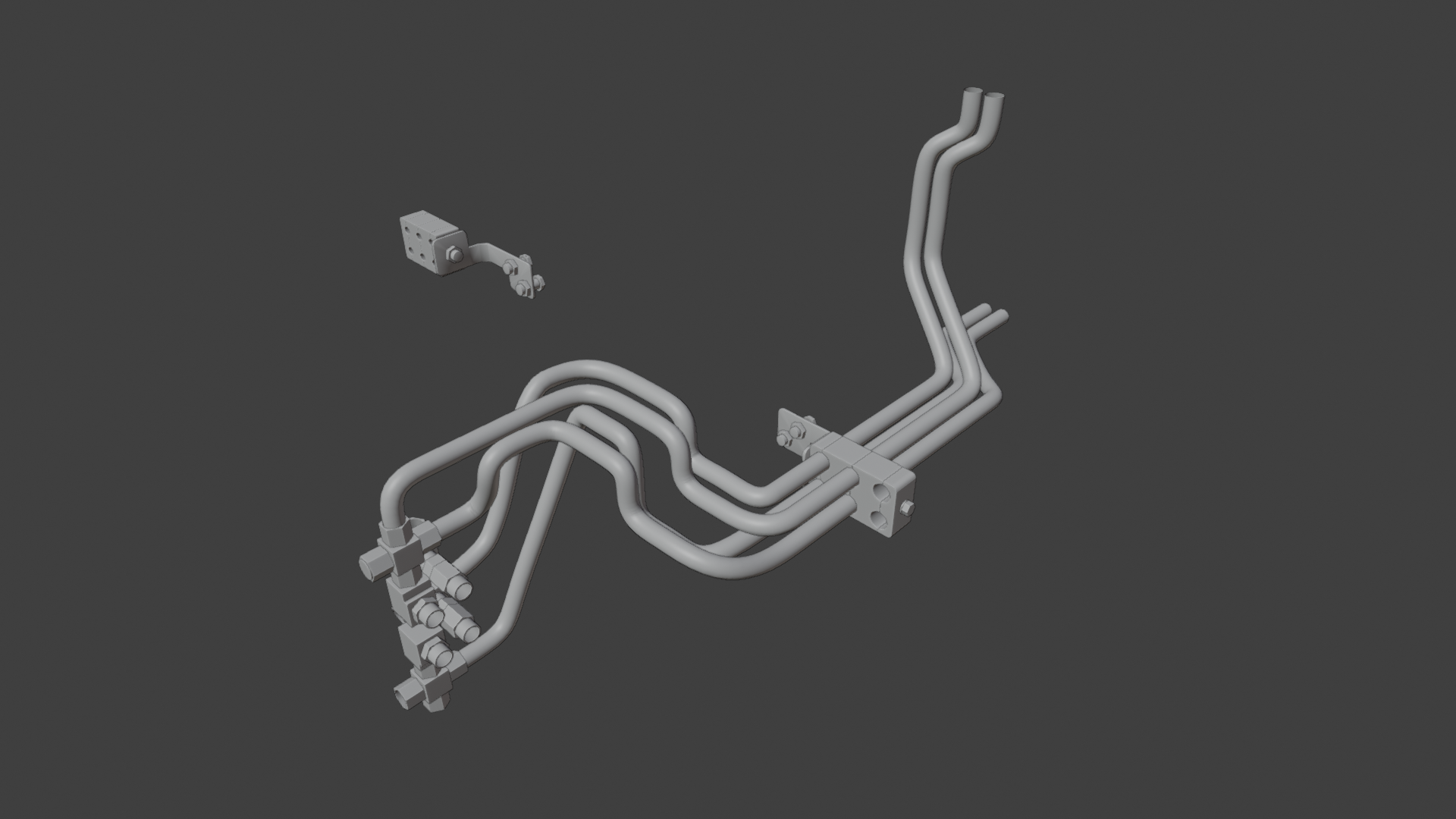
![]() blanchsb ppfbourassa Still need to add a line for the bucket and repeat on the other side and add the connections to the ends of the lines.
blanchsb ppfbourassa Still need to add a line for the bucket and repeat on the other side and add the connections to the ends of the lines.
Not sure how the two brackets fix to the chassis, cant find an image to show this.
Looks great @adrian2301
No that should be plenty for me to work with I am glad I didn't go down any farther or we would have been duplicating the effort.
Let me know when you are ready enough to give me a copy and I will begin routing my hoses to their connections.
I want to add a couple of bits to the control valve. So I should be done by tomorrow.
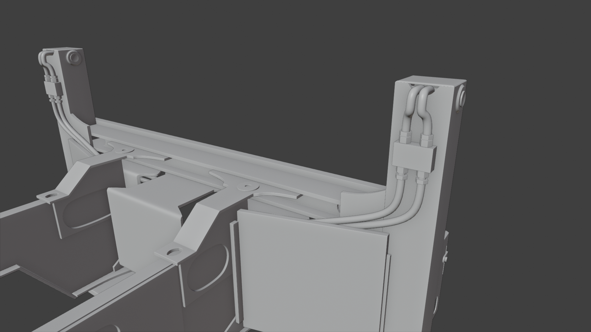
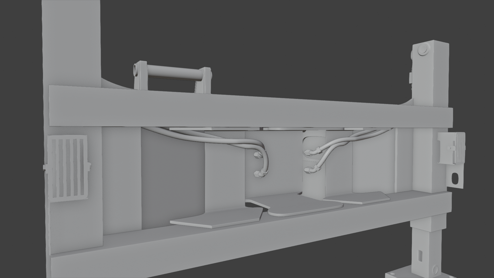
Done the stabilizer hydraulics. ![]() jakeblended they just need to be plugged into the control valve behind the swing frame.
jakeblended they just need to be plugged into the control valve behind the swing frame.
Thanks. I had a late night trouble call and then I got distracted setting up my motion capture Kinect rig for my PC. Wow that was a doozy to set up but man it is pretty slick deal for only $130 and 4 hours of computer issues, lol
I'll take a look at it hopefully tomorrow and work on it over the weekend
@adrian2301 take a look at my post regarding the bezier radius versus diameter on our main thread. We made our stuff double the diameter on accident......