The process you use to put together your 3D model determines a lot - how easy it is to edit later, how good it looks when lighting and shaders are applied, how easy it is to deform while animating, and much more. A good model is crucial for all of the other parts of the CG pipeline to work well.
Messy topology, on the other hand, can make the rest of the process a disaster.
🍪 Download the Art of Good Topology PDF Guide
What can you do to keep that from happening? Here are 8 tips you can use right away.
Contents of this article:
8 Tips For Great Blender Topology
1. Understand Common Mesh Tools
This is an obvious tip, but one that everyone venturing into 3d modeling in Blender needs to become proficient in.
When modeling, understanding how to properly add/remove/modify the mesh s the most important aspect. After all, 3d modeling is all about conforming faces/edges/vertices to form a visually pleasing shape.
So let's take a look at some of the most common types of tools you'll use when modeling. (Note that most of these tools can only be accessed when in edit mode in Blender .)
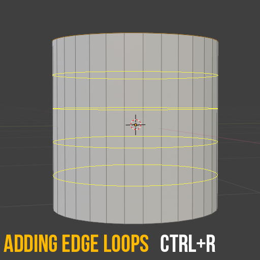
Adding Edge Loops
Adding edge loops is something you'd typically do to support the edges of a mesh to create a crisp-looking edge, or just to provide additional geometry very quickly.
The shortcut for this is Ctrl + R.
When this is enabled, you need to hover over the mesh itself which will then reveal a yellow line to project where this edge loop will be placed. To increase the number of edge loops, use your mouse scroll wheel or type in the number of loops you want using the numeric keypad.
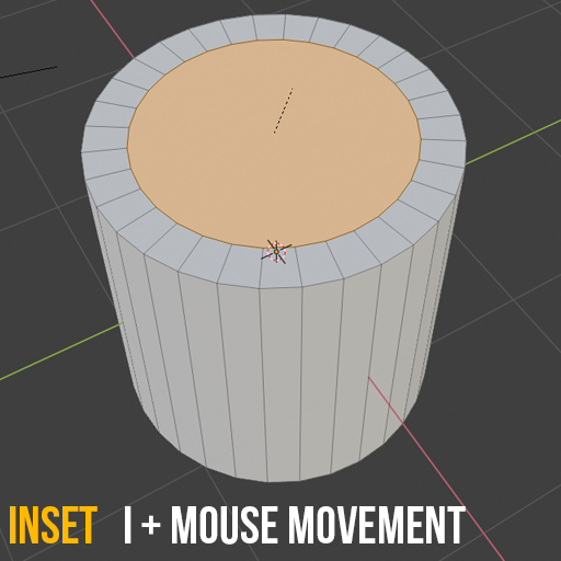
Inset
Inset allows you to create things like a window. If I click a face and press I (as in Inset) with a face selected, I can then move my mouse to create a smaller version of that face within. This is incredibly useful for creating something like a frame or an edge around a specific part of the mesh. Note that this creates the face on the same surface as the face selected and does not change it's shape.
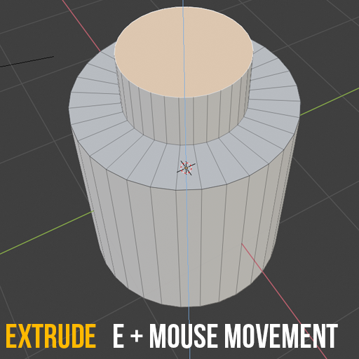
Extrude
Similar to Inset, Extrude also creates additional geometry but unlike Inset, it allows you to change the shape of it by allowing you to take that extra geometry and move it around.
To extrude a face press E (as in Extrude) then move your mouse in the direction you want to extrude to. Typically, this will default to the axis this face is pointing in, but you may also see that you can move the extrusion in any direction you want. Left click again in order to stop moving.
Along with the basic extrude you also have a number of different wants to extrude. To access more extruding options press the shortcut keys Alt + E which will open up the extrude menu. If you have vertex selection mode enabled you'll see all the options available to you to extrude.
Often times you'll need to realign vertices to conform to a proper shape and while you can try to push and pull verts this can lead to a frustrating process of trying to get vertices in line properly. Vertex Slide allows you to move vertices in line with the edge(s) they are connected to. Think of it as being connected to a rail and the rail is an edge. In order to enable this you can press G twice with a vertex selected. If you accidentally slide a vertex, you can right click to cancel the movement.
The same can be done with edges to speed up the process. If you need to slide an edge into place while keeping it along the same surface use the same shortcut key.
 Recommended: Mesh Modeling in Blender
Learning modeling in Blender? This course will take you through mesh modeling workflows and useful tools. Included is a mini-project for practice, plus a modeling exercise. Watch the trailer.
Knife Tool
As the name implies, the Blender knife tool allows you to cut into your mesh. You start by pressing K which enables the tool to appear followed by a knife icon for the cursor. You select an edge to add a vertex point to start off with, then connect it to another edge. Once you're done making your cut, hit enter to save your changes.
By pressing C you can constrain your cut to 45-degree increments. This is useful for getting those perfectly straight cuts in your mesh. Lastly, if you need to make multiple cuts (that are not connected) you can press E to start a new cut. You'll still need to save your changes by pressing enter.

Connect
Connecting vertices is a common way to easily create an edge between two selected vertices. Select at least 2 vertices and press J to connect them. This is similar to cutting through faces with the knife tool but much quicker.
Fill
Similar to Connect, you can also fill in faces. Select the vertex points you want to connect with a face, then press F. You can create an n-gon, triangle or quad with this method and you can also use this to create an edge between two vertices.

Subdivide and Smooth Shading
These can be found under the same Right-Click Menu but are context-specific.
If you are in Object Mode, right clicking will reveal smooth shading, which will smooth out the mesh and remove the faceted look. This is typically something you'd enable after applying some subdivisions to the mesh. This is similar to adding a subdivision surface modifier with simple enabled. Subdividing quickly adds in more geometry and evenly distributes this new geometry throughout your mesh.
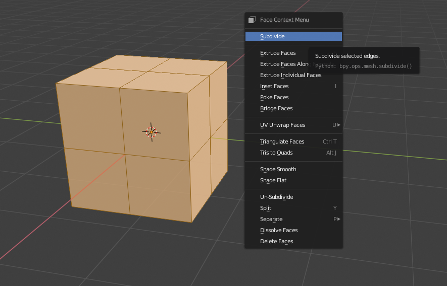 Right click to Subdivide in edit mode
 Right click to shade smooth in object mode
These are just a handful of the most common tools. Being familiar with how these are accessed and when to use them will improve your topology workflow.
2. Know When to use N-gons, Triangles, and Quads
N-gons are polygons that contain 5 or more sides. For example, a pentagon is considered an N-gon. Because of their odd shape N-gons can be difficult to subdivide and you may see odd shading artifacts. This becomes an even bigger issue when animating an object; if you try to bend a face in half you'll get unexpected results.
But N-gons are not always going to be avoided, so you might as well get familiar with them.
 Top face of a cylinder is an N-gon
Jonathan Lampel, CG Cookie's Blender trainer, says:
N-gons are good for complex, flat shapes that won't be animated or have subdiv. It's pretty niche, but that's where they can beat quads because they're faster to work with. Just be careful to convert them to tris or quads before UV unwrapping.
Triangles aka three connected vertices are the simplest way to create a face. Because of their simplicity, you'll find that games utilize meshes as triangles. If you imported a model made entirely of Quads into Unity, you'll see it gets converted into triangles. Triangles introduce poles for just about every vertex. (Poles are 3, 5 or more edges connected to a vertex and these produce their own problems which we'll discuss later.)
 Icosphere is made entirely of Triangles
Lastly, we have Quads. Quads have 4 edges and 4 vertices making it easy to subdivide. This also makes them great for things like sculpting or utilizing them within a game engine which will eventually convert these quads into triangles.
Along with using quads, ensure that these are properly scaled. Elongated faces will result in stretched textures and can deform your mesh topology. Quads not only make for clean topology - they also help display the proper shape and "flow" of your mesh.
 UV Sphere is made mostly of Quads
3. Understand Edge Flow
We talked about N-gons before along with triangles and these could introduce something known as a Pole. As I mentioned above, Poles exist when we have a vertex with 3, 5 or more edges connected to it.
Why is this important? Because poles essentially control the direction of your topology. Understanding how to control the "flow" of your topology is vital to getting specific details in place. Moving and placing poles down to control the flow yourself is highly dependent on the model you're working on.
If you're interested in learning more about how to control poles and edge flow, I'd highly recommend watching this lesson on Edge Loops in Blender by Jonathan Lampel from his Mesh Modeling Bootcamp.
In that course, Jonathan also discusses All Quad Junctions which includes this graphic to better understand how poles could affect your topology:
 Credit to Don Newman
4. Use MatCaps
MatCap (short for Material Capture) is a complete material that allows for proper lighting and reflections. MatCaps help us see how light and reflections react to your mesh topology. It's a very easy and quick way to determine if your mesh is distorted due to bad topology.
Below, we have a scene with traditional shading. While we do have some lighting and shadows, it may be difficult to see distortions in something like a reflection. Instead of creating a reflective material and shader in Blender we can quickly change the viewport shading to using a MatCap.

I've applied a MatCap that includes a very glossy and reflective surface. Now I can quickly tell if any distortion appears within the smooth curved surfaces of this object.

To add a MatCap you'll need to access the viewport shading menu:
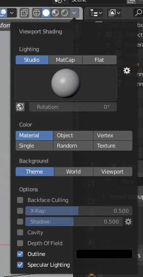
Ensure you have Solid as the display method (the solid white circle) and when you open this up you should immediately see an option to switch between Studio, MatCap and Flat for the lighting. With MatCap selected I can also change out the type by clicking on the preview of the material:

5. When to use Creases versus Holding Edges
There will come a time when you add a subdivision surface modifier to a mesh with flat surface and you'll see those edges start to droop or lose their crisp edge.
There are a few ways you can keep the smoothness of the modifier while still keeping those edges crisp. The first method: using a crease.
Creases are applied directly to an edge and you can make these sharp by increasing their crease value, sometimes also known as their weight (which is a value between 0 and 1). Select the edge in edit mode, then use the keyboard shortcut CTRL + E (same as the edge menu) then move your mouse in or out to adjust the crease weight.
As you may have guessed, creases can only be applied to specific edges. If you have a very smooth mesh but want specific parts of it extra sharp (such as the body lines on a vehicle), using creases might be just the thing you need. Here's an example of a basic cube with a subdivision modifier applied and the top 4 edges have Edge Crease enabled with a value of 1.

Holding edges are typically recommended due to the amount of influence you can have on the mesh in general.
Similar to a tent, the more support poles you provide, the more distinct the shape will be. Holding edges, also known as support loops, allow you to create extra geometry around edges to ensure they don't droop. More geometry in one area leaves less room to "blend" between edges. The downside to this is that added geometry can cause issues with the rest of the mesh topology.
Take a look at a similar example, a cube with a subdivision modifier - but this time, we have holding edges supporting each corner:

Here is another example of both, but with the cube on the left containing nothing but creases. This means less geometry which may be useful if you're really tight on how much geometry you can include in a scene or object but has it's downsides as you can see:

6. Keep It Simple, Stupid (KISS)
This is largely dependent on your mesh, but often you can break it up to ensure that detailed pieces don't make the rest of your mesh denser than it needs to be.
Think about a car door handle. The car door itself can be relatively simple geometry-wise, but a door handle has a key hole, handle and frame around that handle.
The handle will be more intricate. But why should the entire door provide supporting loops and geometry for a smaller piece? It makes sense to create the car door and the handle separately. You can get as detailed as you want with the door handle, while the door keeps it's low polygon count.
Along with that, determine the bare minimum of edge loops needed to form the shape you're looking for. It may be tempting to add in a ton of loops early on to make something look better, but the more geometry you add, the harder it becomes to work with. Limit your loops early on to create what is needed, then add more where necessary.
7. Beware of Duplicates
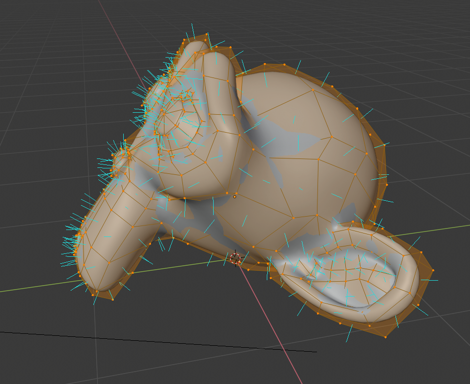
When you start using tools like Inset and Extrude you may forget to move the added geometry which leaves duplicates in the exact same place. Depending on what was duplicated it may be difficult to really see the changes made, but will become apparent when you try to manipulate the mesh in those areas. Take a look at the image below: can you spot the duplicate vertices?

Here, I extruded the top face by pressing E but then hit enter. Sometimes you may accidentally hit enter or think you canceled the operation when all you really did was leave it in place. I can select the top face and move it up:

If you suspect you may have duplicate vertices, you can select the entire mesh and use shortcut key Alt + M to pull up the Merge menu. You'll be provided options to merge vertices (assuming you have more than one selected) based off the center point, 3d cursor, or to collapse them into one. The last option is By Distance which was previously known as "doubles". If vertices are close enough, they will be merged together. 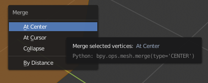
8. Always Check Your Normals
Similar to duplicate geometry, you may notice that your mesh appears darker than normal.
First off - what is a normal in Blender?
Normals refer to the direction of the faces. Here you can see blue lines indicating the direction each face is pointing in:
 If you want to enable this yourself you can find this setting under overlays at the bottom where it says Normals. You can select Vertex, Split or Face normals along with a size for the length of the blue line:

From time to time you may be working on a mesh and end up in a situation where your normals are flipped in the opposite direction. While this mostly affects the rendering of your object, it may confuse you into trying to fix the issue by adding more edge loops or modifying the mesh.
Below is an example of a couple faces of our mesh flipped. The faces still exist but because they're pointing in the opposite direction they result in weird shading. In rare instances you may also have issues creating edge loops through these areas. By enabling the normals display you can see which faces have issues.
In general, flipping normals is done all at once. To open up the normals menu use shortcut Alt+N. Next, you can recalculate outside to have the normals pointing outward.

In rare cases, you may be building a model where the inside is rendered in which case you'd want to recalculate the inside. This is also important when working with games. You may export a model and notice that mesh looks transparent and only the inner portions are rendered:

This is due to the normals being flipped. Typically you only render one side of a mesh as there's no point in rendering parts of a mesh you won't actually see (which also helps with performance). If you experience this when importing into a game engine you'd have to recalculate the normals to the outside in Blender and reimport that once again. Make sure to check out my article on Maximizing Your Unity Game Performance as well.
Retopology Tools
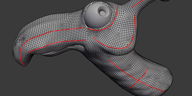
Once you get to a point where you are working with higher density mesh models on a regular basis you will want to speed up your retopology workflow.
Retopology is the process of turning dense topology into simpler, lower poly topology. This is especially useful when working with game assets or animations, where sculpted objects will be too costly to utilize or provide improper deformations.
RetopoFlow
RetopoFlow is retopology suite created in house by Jonathan Williamson and Jonathan Denning and can be found on the Blender Market. You can watch a free course on how to use RetopoFlow addon - prepare to have your mind blown!
DynRemesh/AutoFlow

DynRemesh 2.5 is a quad-based remesher for Blender 2.8, assisting in retopology for your dyntopo sculpts & 3dscans containing too many triangles.
Tesselator
Tesselator is a remeshing addon that helps you create regular quad and triangle meshes easily out of sculpts.
Where to go Next
For more in-depth tips on proper topology and tools within Blender, check out some of our most popular Blender tutorial series:
Recommended: Mesh Modeling in Blender
Learning modeling in Blender? This course will take you through mesh modeling workflows and useful tools. Included is a mini-project for practice, plus a modeling exercise. Watch the trailer.
- Modeling with Good Topology (Live Stream) by Jonathan Lampel
- Mesh Modeling Bootcamp (tutorial series) by Jonathan Lampel
- Introduction to Retopology (tutorial series) by Jonathan Willamson
Those are just a few of the courses we offer that can speed up your topology work flow. Have questions about your specific model? Feel free to post questions and comments on our community forum.
Have any great topology tips and tricks you'd like to share? Let us know in the comments!
Great post >:P
Very nice, Thank you Jonathan for thist guide.
One Question... I once tried (actualy many times) to model a golf ball. I use an Icosphere but I can't figure out how to get equal sized faces... at the end, some of the holes come with different sizes... why is that. Shouldn't have the faces from an icoSphere have the same size... or is it even impossible to create a Golf ball with the same sizes of holes.??? I ponder 😕
Thanks Jonathan - nice tips, I like the little animations which SHOW the reader how things should be done
Keep'm coming!
Thanks everyone, glad you all enjoy it. A lot of this stuff gets lost in various lessons and tutorials so it's good to have a reference for it that you can easily review in an article.
ty, Jonathan
Jonathan this article is brilliant!
Thank you for making such summary in non-video format, because sometimes it is much easier to memorize like that
Excellent article. Really covers the ground well, and nice to have it collected.
Thanks for this!
Not sure if this would be going 'too advanced', but I feel like it's worth noting in the 'inset' section that holding down CTRL while insetting pushes the surface in or out according to the normal. I use it a ton and it's often a really useful and quick way to manipulate the mesh on curved / more complex surfaces.
In any case, this is a nice quick and informative article for people just starting out!
Thanks, Jonathan!