Decided to try and add Blender to my toolbox. I've dabbled in the past but never really committed myself. Quite the change coming from parametric and direct modelling.
Anyway, I'll be keeping track of the stuff I've done so far here. Not entirely sure what the standard is, and if it's accepted to show non-CGCookie stuff. If not, I'll remove it, but for now, thought it'd be interesting to see how I progressed since I picked up Blender again.
I'll list the non CGCookie tutorials first:
The Doughnut tutorial from Blender Guru.
Also did Blender Guru's Anvil Tutorial:
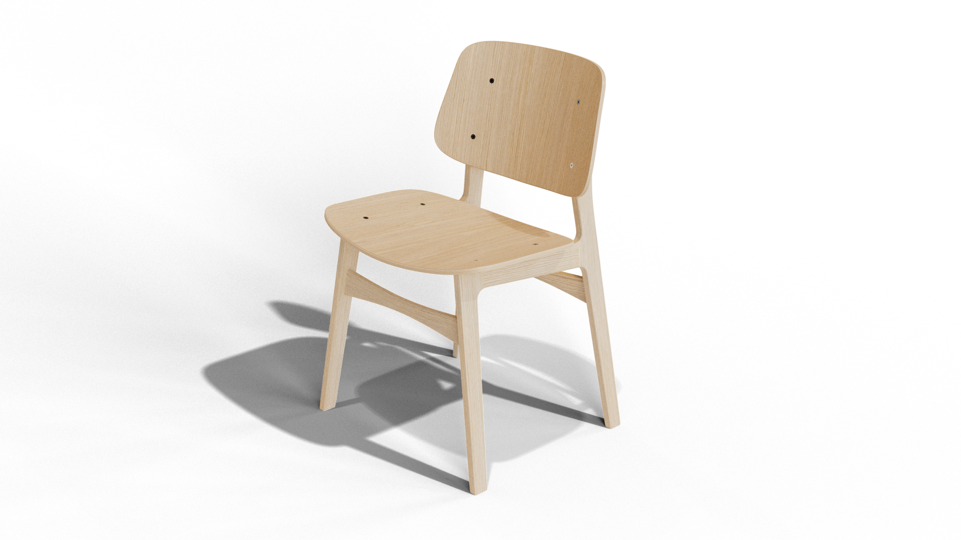
And lastly from Blender Guru, his recent chair tutorial:
Also did some of Grant Abbitt's tutorials:
Made the goggles before watching the full tutorial. Quite pleased with how they turned out, but did make a few choices that made it significantly harder for myself. One of them being that the frame is one object for both the leather and the metal parts.
Now onto CGCookie stuff
The low poly rocket:
Loving the low poly style, and most likely will be trying more of it in the future.
I then followed the link at the bottom, which led to the 2.79 blender tutorial, which ended in an assignment to make a wheel. I picked a wheel from the Curiosity Rover, which turned out quite a bit harder then expected. You can click here for the Sketchfab link.
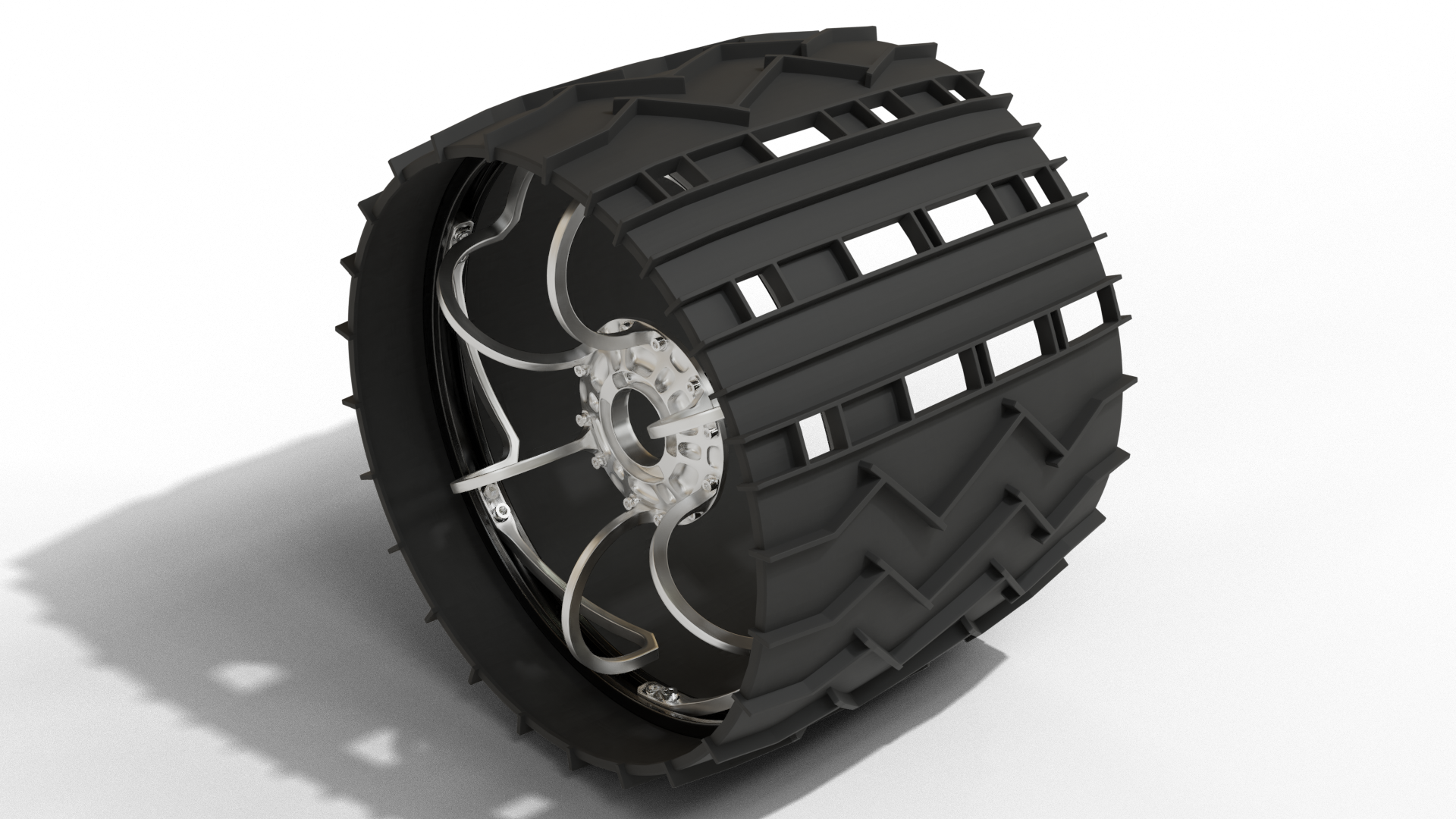
Ran into some issues creating the zig-zag tread. The first few tries I had I ended up with parts of the tread being thicker then other parts because of the rotation I used.
Another issue I ran into was with the faces of the tire and of the morse not aligning properly. I ended up using a solidify modifier for the morse tread, but even this still has some face problems on the inside of the wheel. As can be seen here.
Looks great Sanne!
Considering what you've already made before CGCookie, I can see a great future for you;)
Really like the wheel, but, honestly, the topology is a mess...the treads are just intersecting, there is way to much unnecessary geometry (especially around the 'Morse code').... still, like I said: it looks really good!
Looking forward to seeing more!
Thank you!
Yeah, I definitely need to work on my topology. It's the bit I'm struggling with the most honestly, I keep approaching problems like I'm parametric or direct modelling, where your geometry just merges. It's gonna take some effort to break out of that line of thinking.
If you happen to have any tips or links to courses that focus a bit more on topology and issues like I'm having with the wheel, I'd love to hear em.
This https://cgcookie.com/course/mesh-modeling-bootcamp is really great to start with, has a lot of information on topology.
It's definitely not the easiest part of 3D modelling, but topology is really important and often even essential.
Also, I happened to have made a small demo recently, which is actually not so much about modelling a tire, but I still had to make one and it shows how you can get a decent result with very little effort. Treads are not separate from the rest of the tire, it's 'one' piece of moulded rubber so model it as one piece (that's my opinion). Just watch the first five minutes or so if you like and don't worry about the drivers part;)
That course looks exactly what I'm looking for. I'll start it after I'm done with the "fundamentals of 3D mesh modeling".
And yeah, that was my first attempt as well, have the treads be part of the wheel. I ran into issues when I tried to create the treads though, with parts of the tread being thicker than other parts. I tried different bevel and loop cut options, but just couldn't get it to work. Eventually I just manually modelled the tread, and used a lattice to get it to align with the wheel. Not a clean solution, but the only one I could come up with that would make the tread even.
I'll take a look at your demo, should definitely help. Thanks for the feedback!
The trick is to use a Simple Deform Modifier, so that you can model a segment complete straight, moving verts along the X-, Y- and Z axes; that makes everything sooo much easier;)
Aah, gotcha. Haven't used that modifier yet, but that does sound like it would make it quite a bit easier.
Took a look at your tire video today. The deform modifier would've made my life quite a bit easier. Looking forward to using it in the future.
One thing I did notice, and was wondering if you might have any input on. When you're creating your tread, you make treads that vary in thickness. This works for your tire, but in the case of the Curiosity wheel the treads are equal thickness all the way.
I ran into problems trying to recreate the equal thickness, and eventually hand modelled the entire tread. Any ideas on how to do make that process a bit easier?
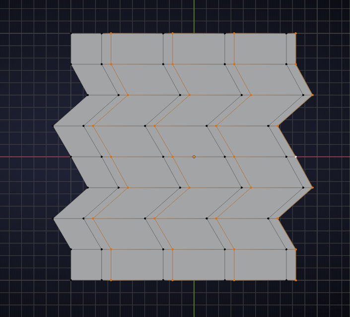
Hi Sanne, I'd probably start with a Plane and make some edge loops and shift a few, something like this:

Move the selected edge loops along the X-axis:
and extrude the treads:
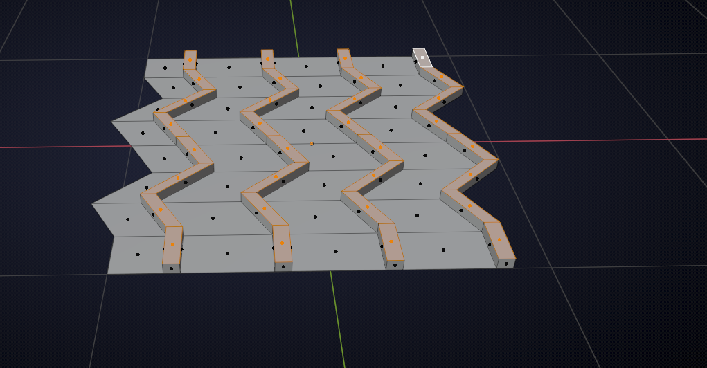
You' have to make a few of those edge a bit longer in the first screenshot, but that doesn't change the principle.
And they are guaranteed to have equal thickness along the X- and Z-axes this way!
If you want equal thickness in the 'normal direction', we would need a different strategy...
Yeah, I mean equal thickness in the "normal direction". Basically if you were to use calipers to measure the tread the red measurement should come out equal to the green measurement.
A lot more work, but start like this:
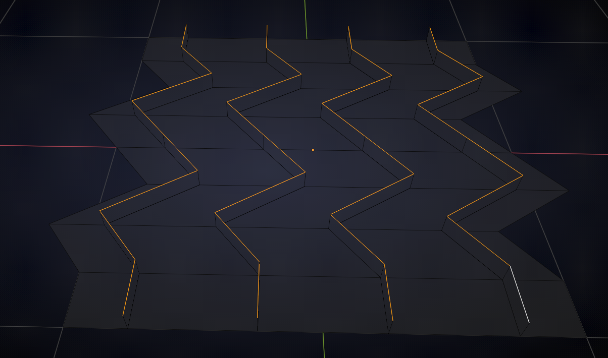
then make sure the normals of all the 'upright' Faces are in the same direction (doesn't matter which direction):
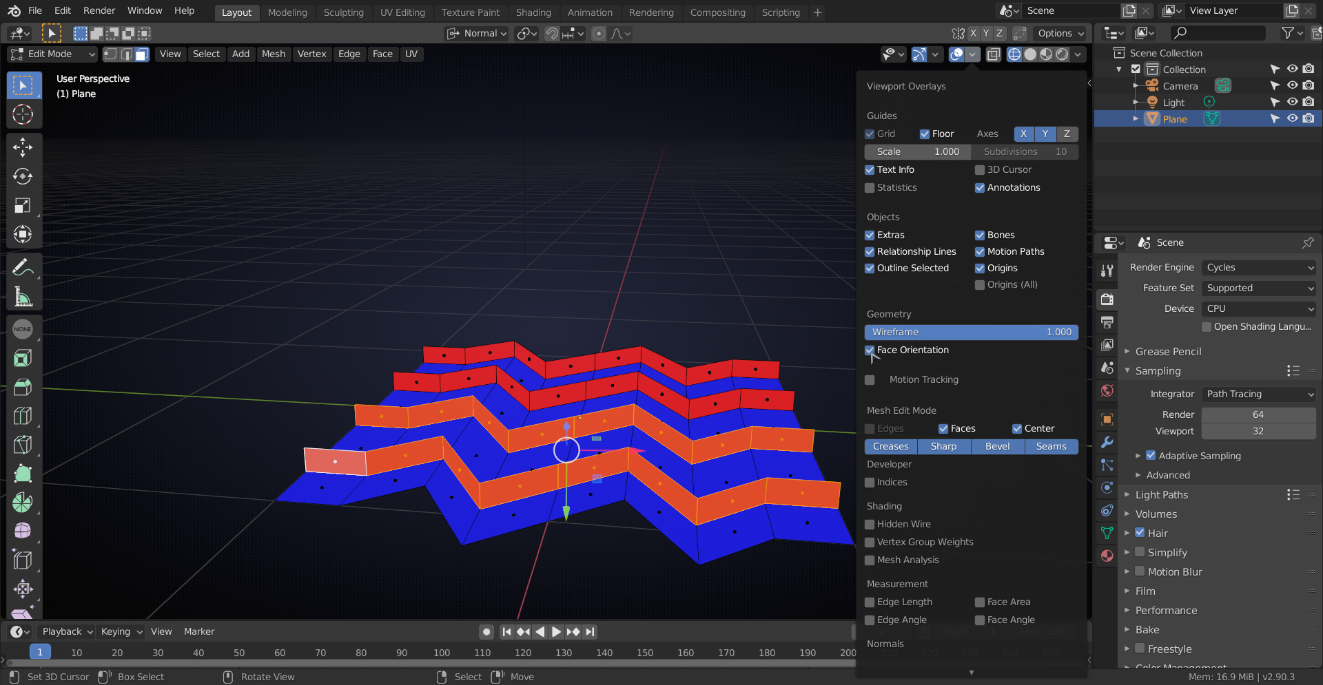
(use ALT+N to Flip the Normals of the Faces that are 'wrong').
Then select paralel Faces and Extrude them all the same distance (here I pressed: E .1):
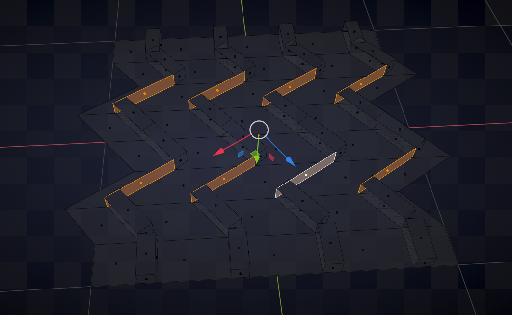
Now they're all even thickness, but there is still a lot of work to be done; fill the holes that came with the extrusions and the delete the (here selected) 'floor' Faces:
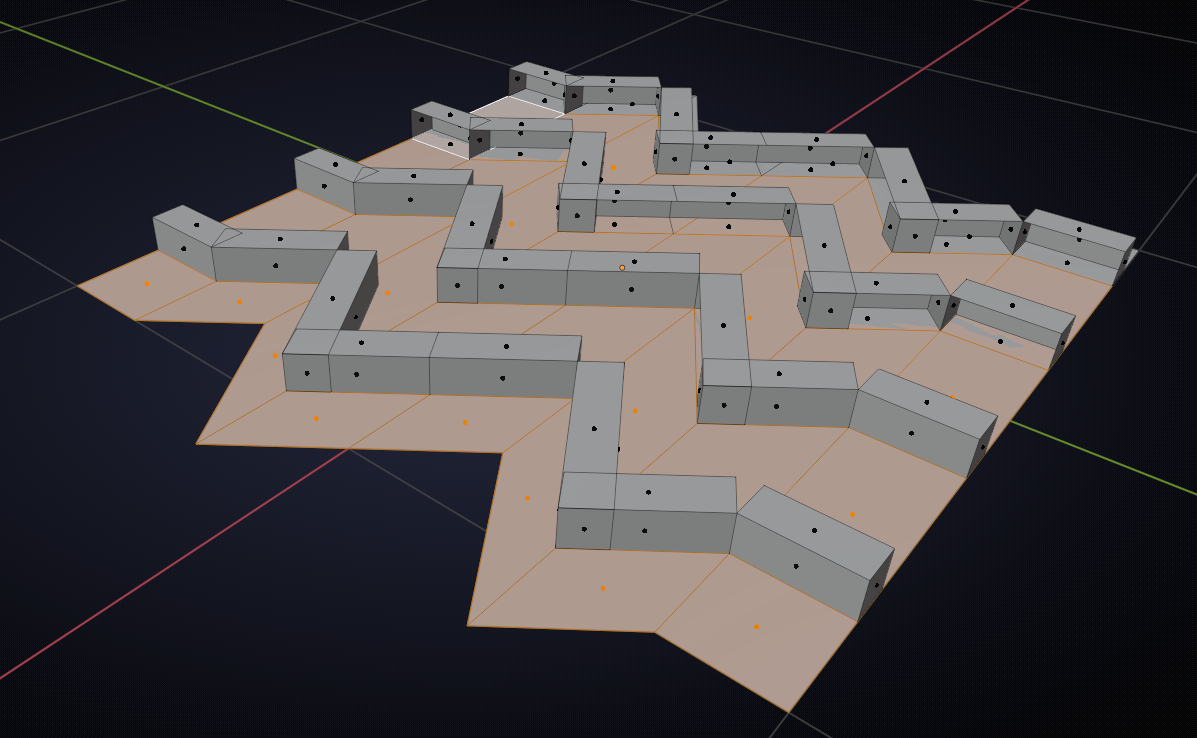
Then extend Edges where needed by making a Custom Transform to get the correct direction:
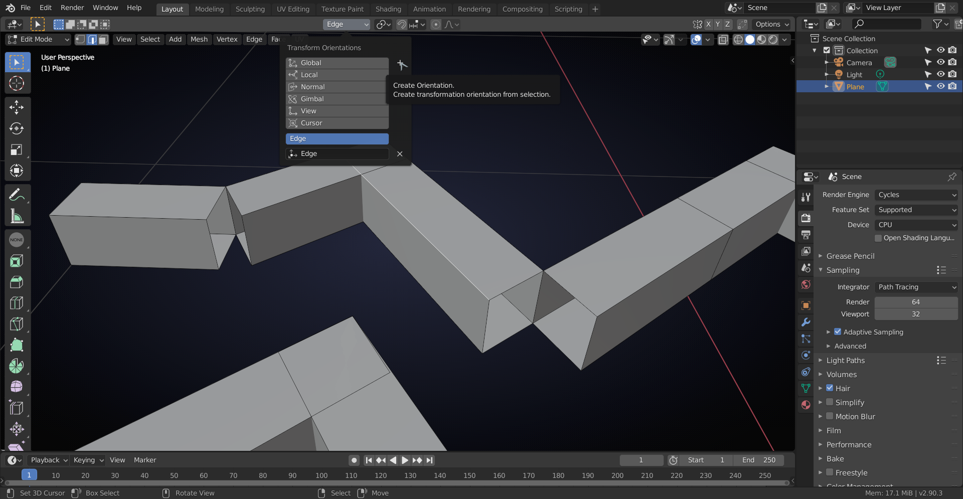
so you can snap the vertical edges to where they need to go:
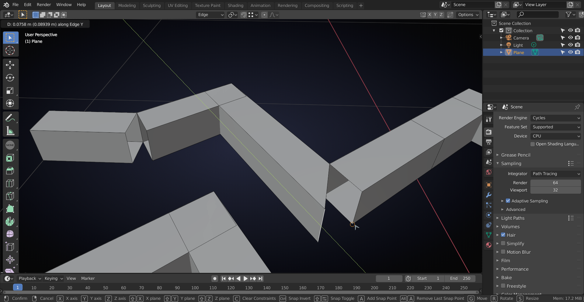
And when you've done all that, Merge by Distance and then simply connect the treads again.
Don't forget to delete all unnecessary Faces...
That did it!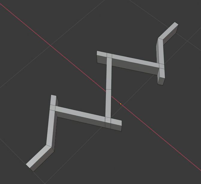
Was a bit of work, but way less then my original method. Thanks!
I also might have found another way to use the bevel tool to make even thickness all the way. Turning off Loop Slide also does the trick.
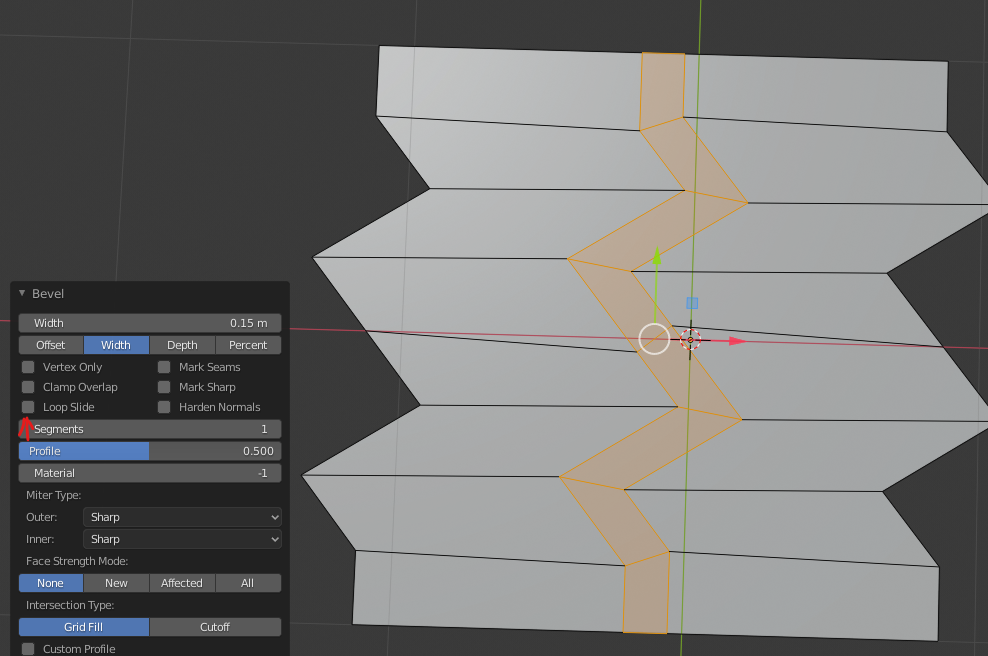
With Loop Slide on:
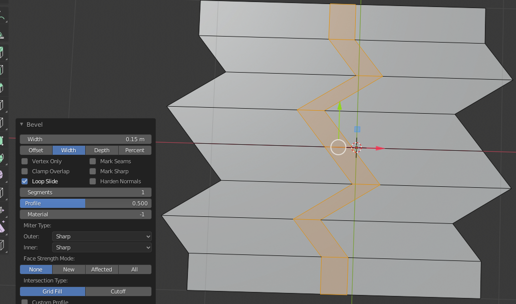
Your method is preferable in my case though, cause the treads need to have those little extensions at the end. Thanks for all the help. Much appreciated.
Thanks for the Bevel trick! I was thinking there should be a way to use the Bevel, but couldn't get it to work this way!
One other problem in this specific case would be that you'd probably want these edges parallel to the X-axis:
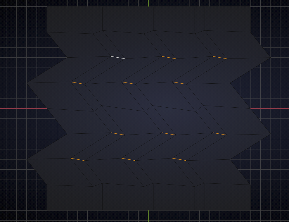
But great to know anyway, I'm sure this will come in handy!
That is a good point actually. That makes that bevel option even less ideal.