@Kent: Would it be ok that I focus mainly on the on wheel's rim and hub for the next assignment?
The front axle and the rear axle aren't only significantly different but also have pieces with complex organic shapes. I've already thought at sculpting but maybe there's an easier way. For the rear axle, I've only found isometric (?) views but no orthographic views. Is there a good method how to handle this in Blender?
PS: Uploading an image here didn't work, so here's a link:
Sure I'm fine with you focusing on the rim + hub. That's within the 25% threshold in my book 👌
The axles definitely a complex pieces by the looks of it...Maybe you can do the rim + hub + front axle and ![]() spikeyxxx could do the tire + rear axle?
spikeyxxx could do the tire + rear axle?
Splitting the two axles between Spikey and me is exactly what has also come to my mind. The axle that I've blocked out is actually the rear axle which I've roughly modeled according to one of the images on your reference sheet.
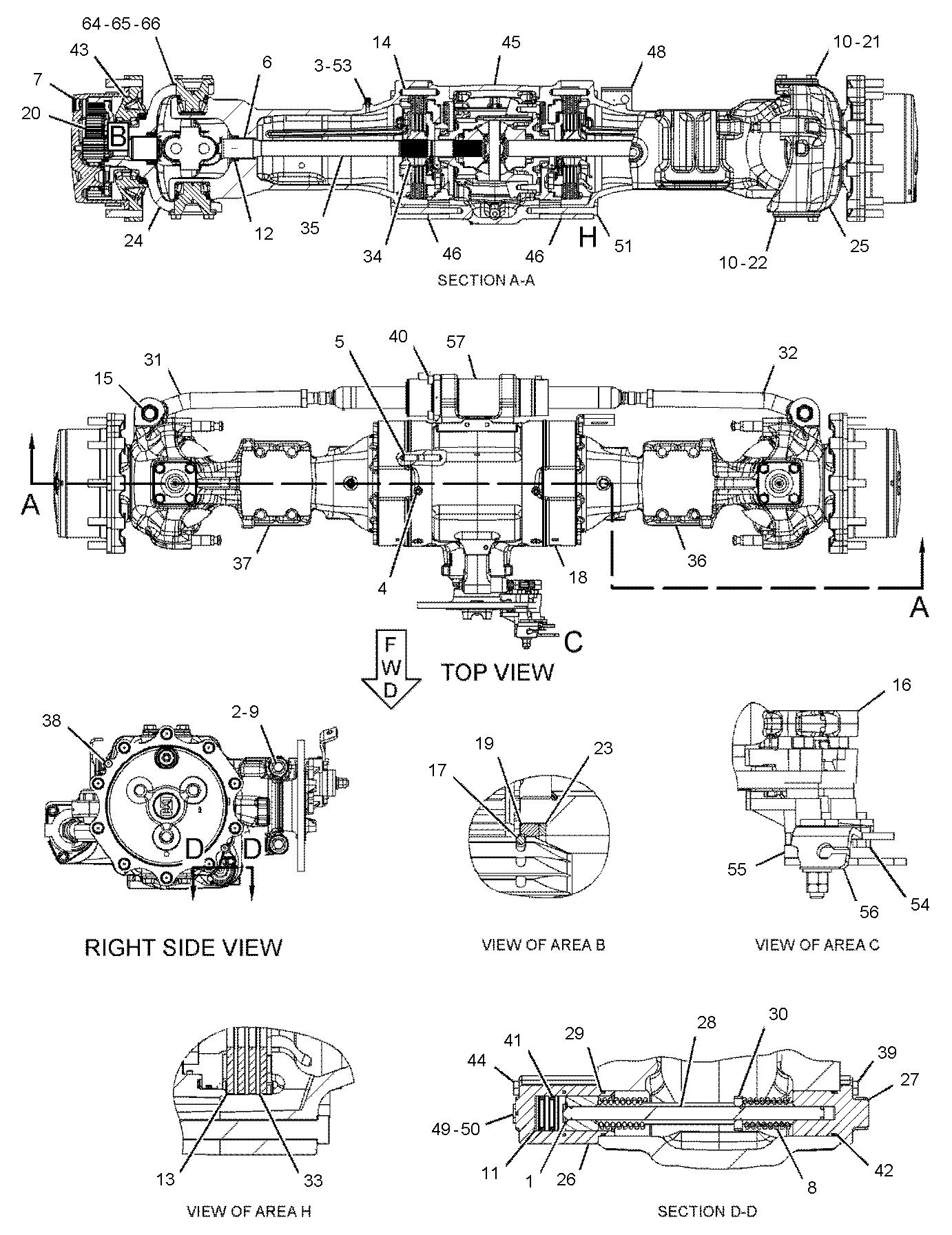
Heureka! I've found an orthographic view for the rear axle here:
For setting up an isometric view, I've found this description by architect Allan Brito:
The isometric view alignment seems to work well:
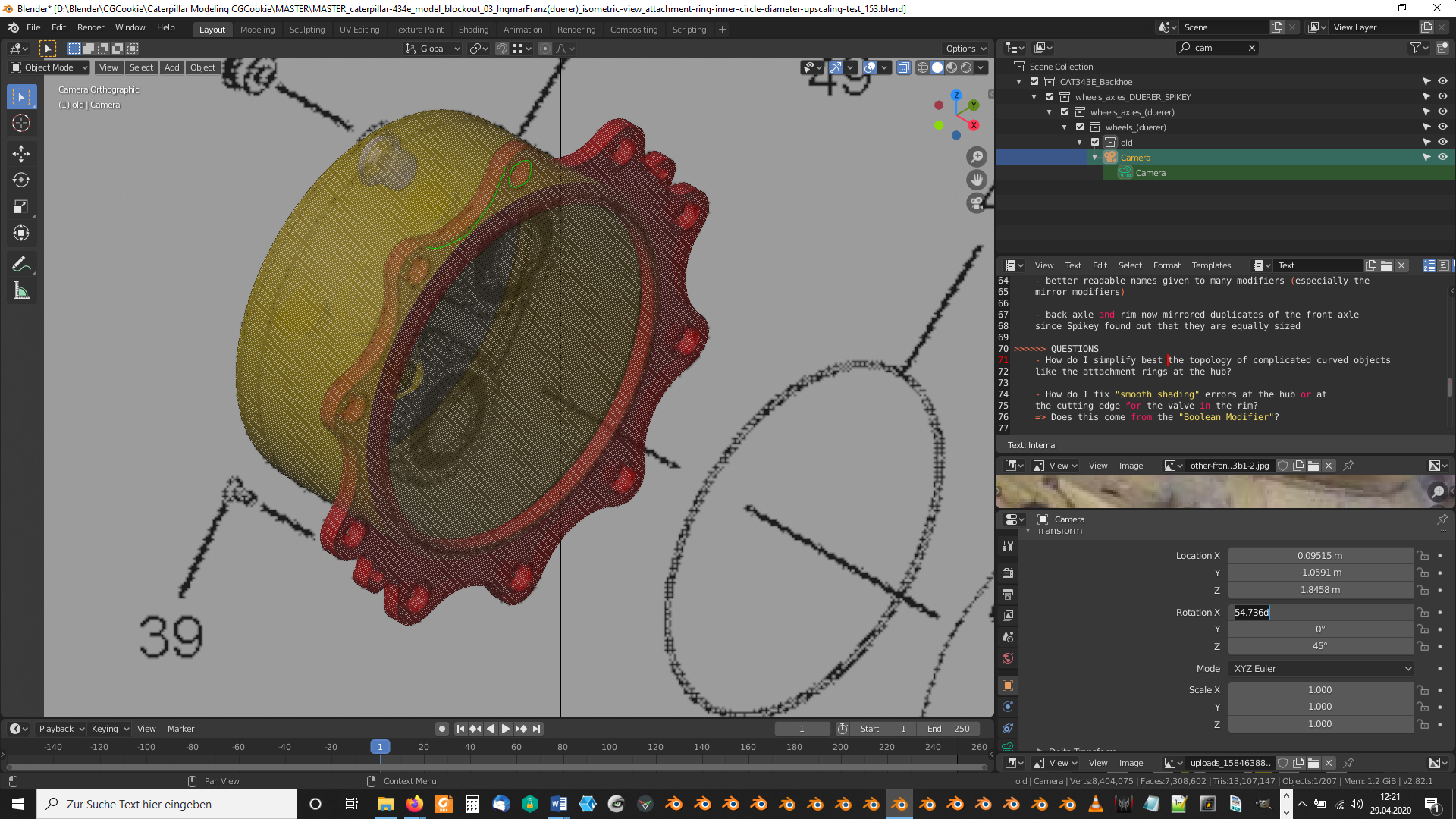
Camera rotation settings (orthographic view) in the lower right corner.
These kind of drawings are called 'Exploded View' and they are only meant to show how the different parts are assembled.
It is possible that (especially with modern CAD-drawings) this gives an accurate isometric view, but I wouldn't worry at all if that is not the case.
If someone happens to stumble upon a hand-drawn EV, things will probably not 'fit' exactly.
So, this is my second rear axle blockout for assignment#2 based on the orthographic and isometric plans mentioned above:
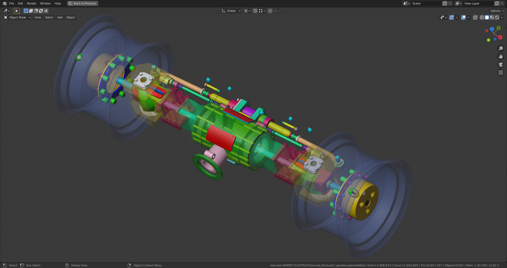
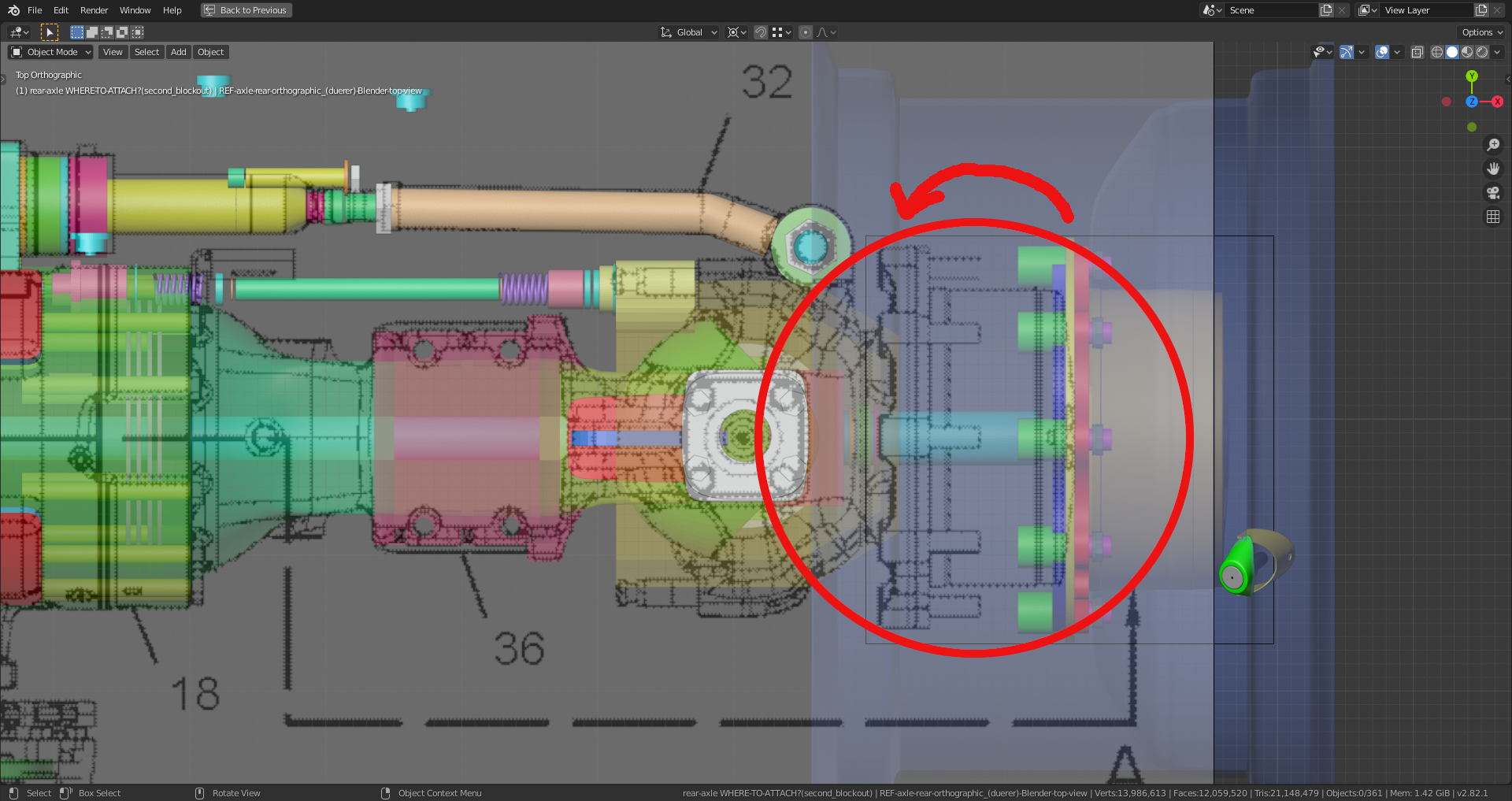
But there seem to be some discrepancies, since these plans show a shorter rear axle than the wheel distance in the official brochure (orthographic views used in livestream#1) suggests:
The file is here.
I can't believe the level of detail you've gone into with your axle ![]() duerer. It blew me away when I opened the file 🤯
duerer. It blew me away when I opened the file 🤯
I also feel your pain regarding the blue prints / diagrams. In my experience they answer questions and raise others frequently. Based on your red circle, the drawing seems to make more sense mechanically. The cyan cylinder in the center of the axle rotation surely couldn't support the weight of the axle housing, much less the entire backhoe.
My question is one of scale. How do we know that the scale of the axle housing model is accurate? Could you simple scale up the whole axle to align with the wheel position? Or does that start to collide with the chassis, engine, etc?
@theluthier about the scale:
here http://s7d2.scene7.com/is/content/Caterpillar/C741034 especially on pages 16 & 17, there are some real life measurements that could (and I think should) be used to decide on the scale of everything; scale the drawings to fit those measurements.
I've scaled up my rear axle by 1.145 after appending the detailed chassis by @adrian2301 and it fits well:
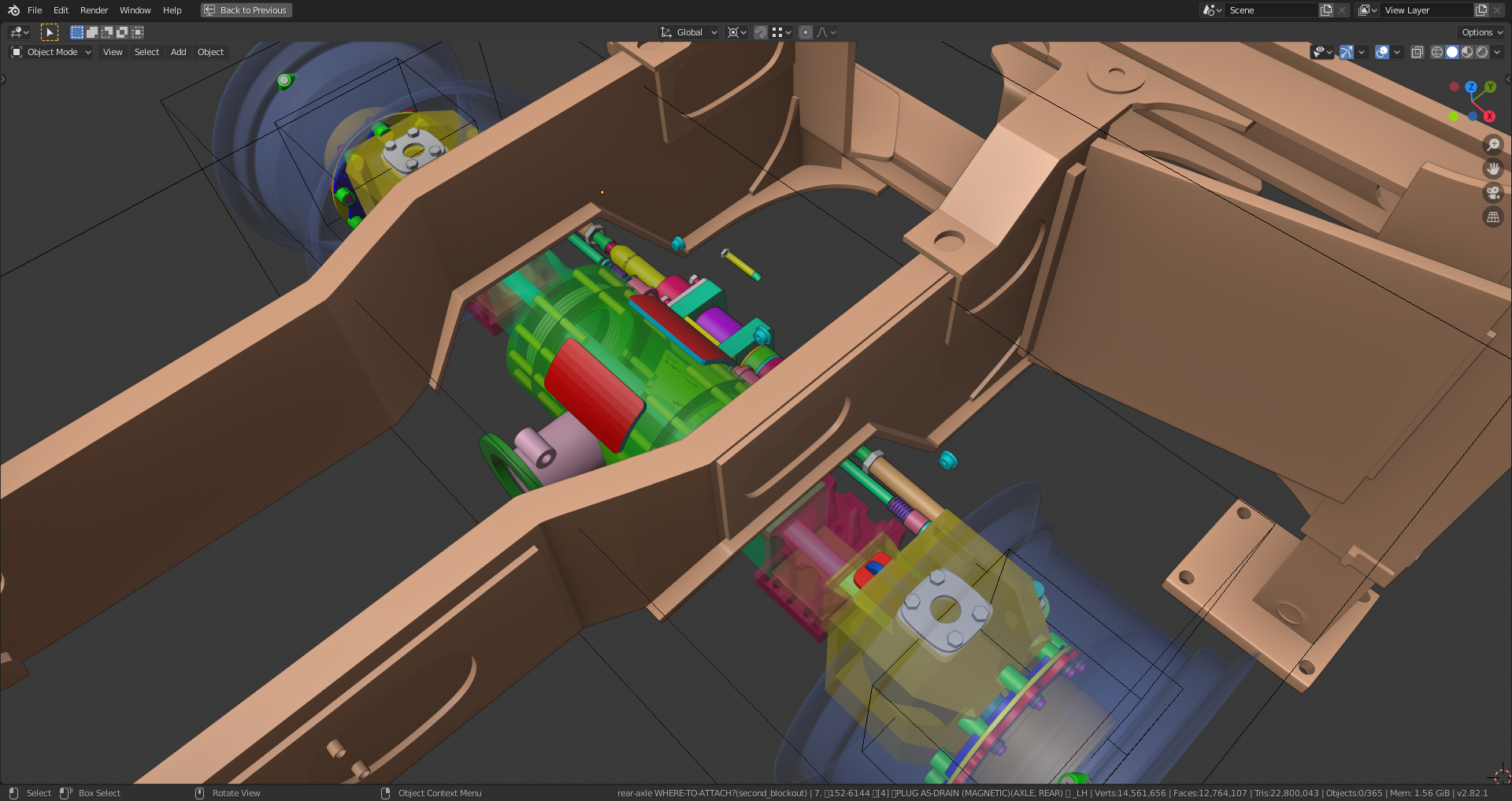
Maybe, there will be minor scaling adjustments necessary with the further detailing, but the blue axle bar now fits well with wheel hub case:
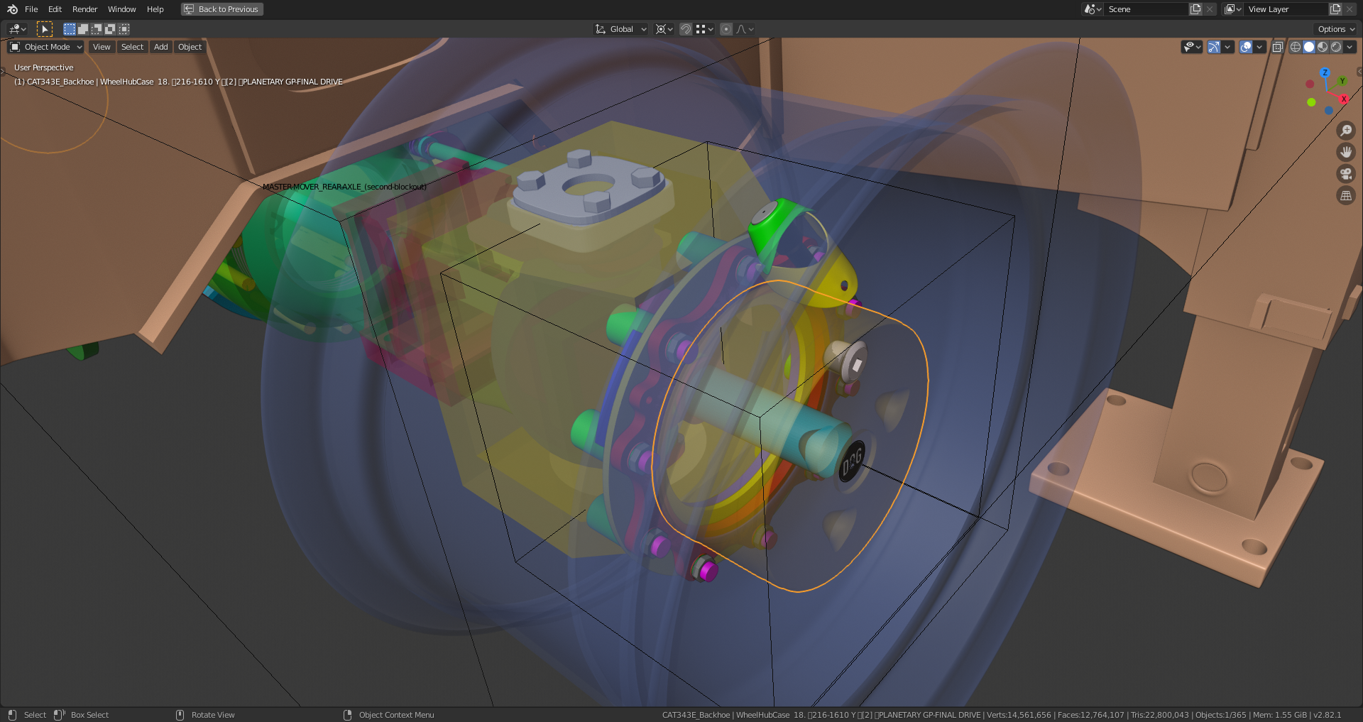
By the way, the wheel hub is home of the planetary gear that I didn't (yet 😉) model:
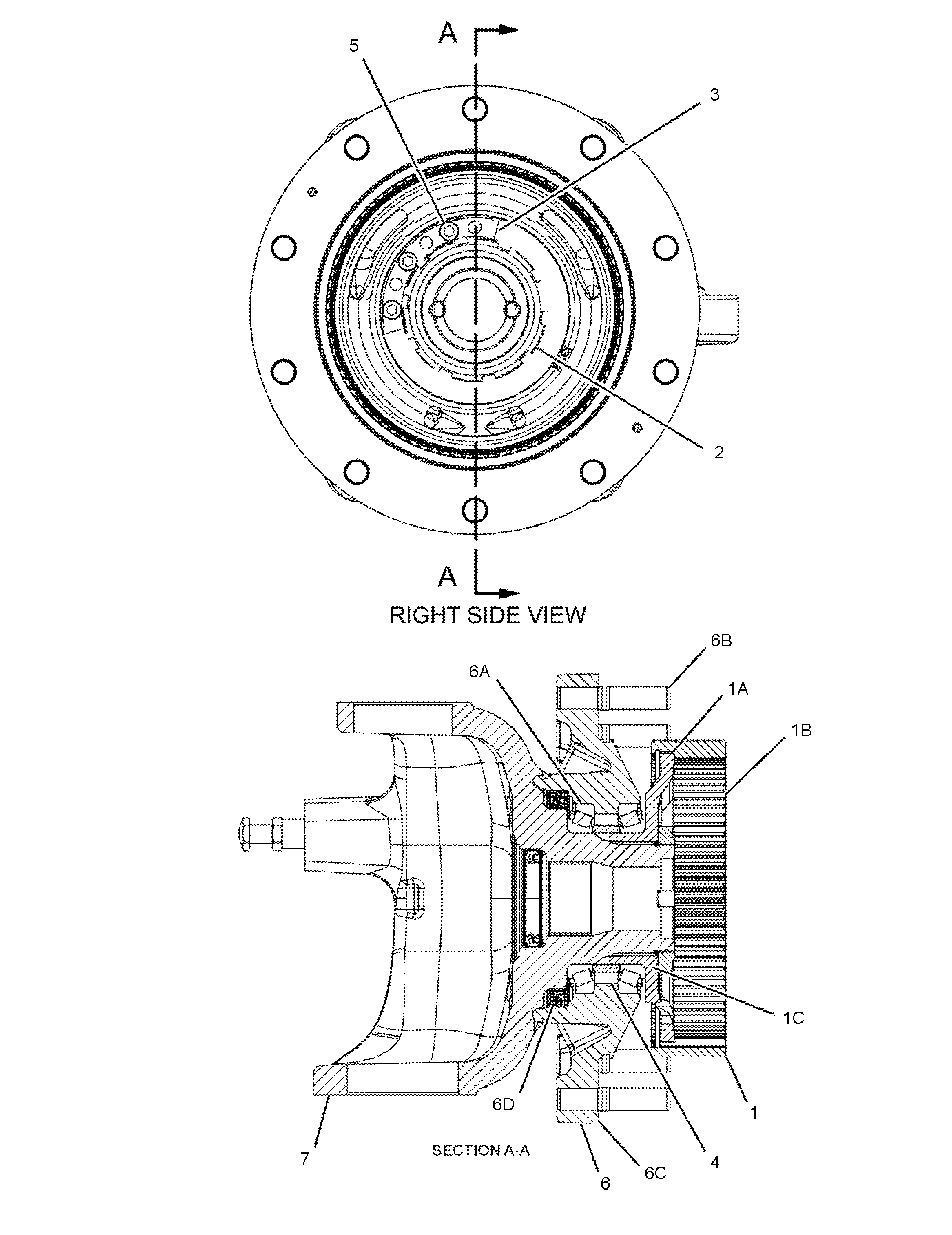
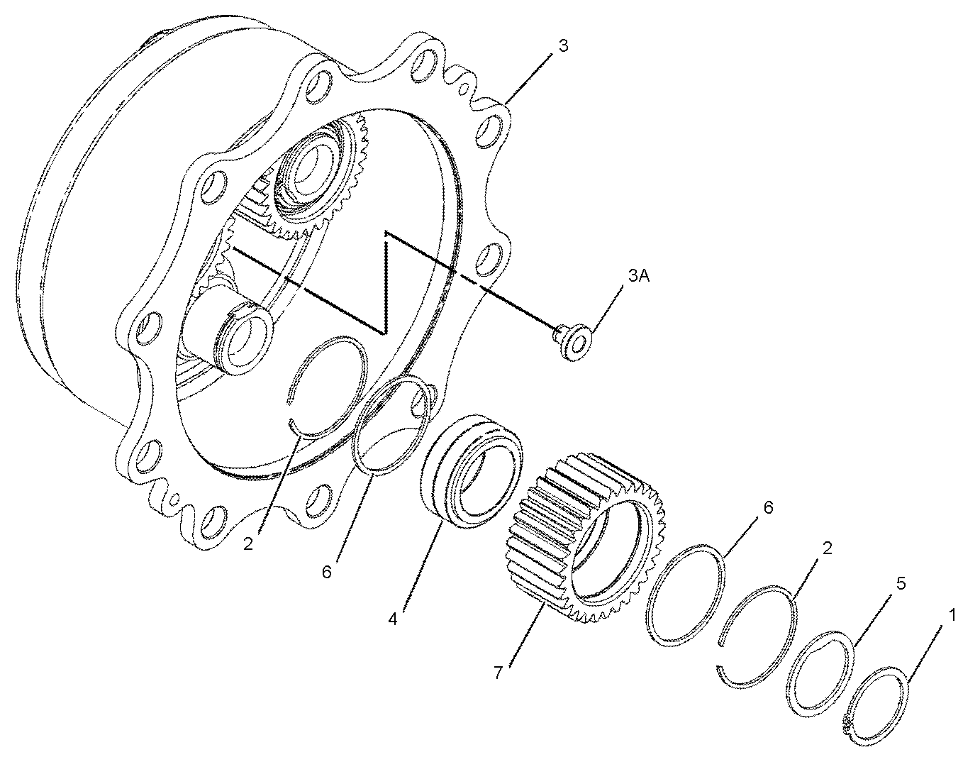
Yessir agreed. I remember beginning that way in the first livestream (according to cab height) but I just checked the distance between wheels (2200 mm) and it's off currently (1996 mm). The cab height is also slightly off, so I must have been a little off when I blocked in the height of the ref 🤔
I will correct the scale for everyone to download by Tuesday's stream.