I am trying to model this little metal clip:
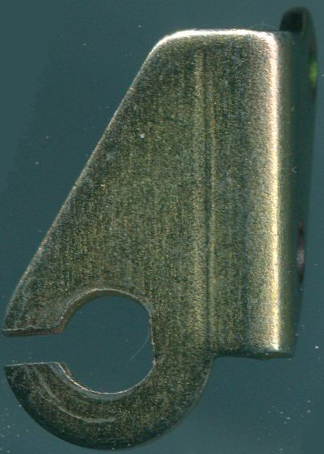
And I want to know if this is a reasonable outline geometry for this face, given that the ring part can (with a little bit of force) be deformed.
Thanks for any input! I've attached the .blend for it at this stage in case it makes it easier to show where I am messing up.
Well your example is like what I would call this flow:
rather than this one:
because it lacks the rings of faces around the holes as seen here:
see:
yours on the other hand goes like:
so while I thank you for taking the time with your answer to model it, I find the answer somewhat confusing. Additionally if your model, rather than the picture of the flow of faces, is the most correct way then I have a question. As far as I can see there is a triangle near the top hole and there are long, thin quads in the middle. Am I incorrect in thinking these are both things that should generally be avoided when possible?
That triangle is not a triangle. You can always spend your time making the quads more smooth. I didn't think it was importend for this example. Also, this object does not have to be deformd so the shape of the quads are not importend. I do have a quad loop around the holes.
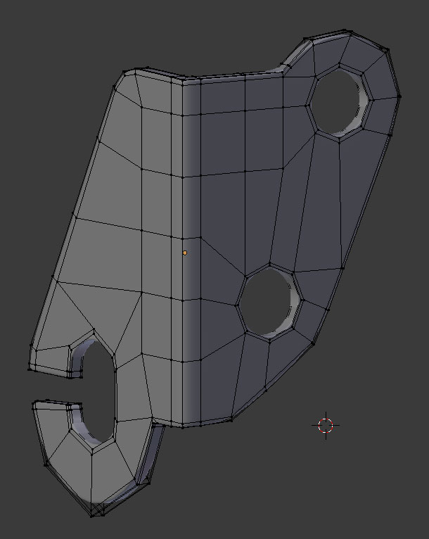
Thanks! I can see now in that larger picture and in the blend what you did.
So I want to check, then, if these are the correct answers to my questions since, as I mentioned, my question is about general practice even moreso than this particular piece:
1. Is the general design of having a ring of faces around screw holes (and the C-shaped hole) an industry best practice?
Based on your version I'm guessing "yes"
2. If so, should it generally be a single ring, or multiple rings? If it varies how I can I learn when to know when to use a single ring or multiple rings? ie is there a general best practice guideline that can be followed?
Based on your version I'm guessing "1 ring" though I'd like to know a resource that will help me better understand this choice.
3. If rings around screw holes is normally a best practice, in a piece like this does it over-complicated the topology and should it be reserved for complex pieces?
Based on your version I'm guessing "no, having rings around the screw holes does not overly complicate the geometry"
4. If the rings around the holes is generally acceptable, are there issues with this specific layout other than the number of rings? For example, can have a ring of faces directly acting as an objects outside edge cause issues? Should I instead create a loop that wraps around the entire outside edge of the object, have the holes have small rings of faces around them, then connect the hole-loops to the outside loop? If single rings are ok, then I assume its ok for there to be a single face between a screw hole and the objects outside edge as seen in the top right screw hole, though to me this seems like a suspect design.
Based on your version I'm guessing "You should have a thin ring of faces around the entire outside edge of the object, a small ring around the holes, a larger ring of faces around the C-Shaped hole.
5. There are three five-sided poles in the current topology. Is it better to keep the overall current design of the topology or try to eliminate or reduce the number of poles? (this is basically another way of saying question 3)
Based on your versions I'm guessing "poles are no issue, make rings around the holes and connect them to the overall structure and don't worry about poles"
Thanks for your feedback on my understanding of these questions based on your model as an answer.
Regarding: "the shape of the quads are not importend"
I agree on the idea based on the model's expected use cases, however I'm trying understand if its best practice to ensure the quads are square-ish or if that is not a best practice and I'm just imagining that.
To understand if it is the general design and an industry best practice of having a ring of faces around screw holes (and the C-shaped hole), you need to know why this ring is for. I’m afraid you do not really understand what subdivision is all about. Here is a drawing.
The black dots are the point or vertices. The red line is the mesh.
Figure 1 does not have a subdivision modifier. Blender draws the mesh –red line- from point to point.
Figure 2 does have a subdivision modifier. But what happens with a subdivision modifier is that blender goes round in corners. The whole idea of a subdivision modifier is to make a smooth surface. This may be kinda inconvenient, it makes a screw hole looks like a sink hole. Therefore you add 2 extra vertices at the corner to force Blender to make the rounding smaller. Figure 3.
Of course the drawing is a 2 dimentional drawing and we work in 3D. Those two extra point translate in 3D by 2 extra loopcuts that create two rings of faces.
Those rings of faces have nothing to do with the general design and an industry best practice. They are there because they are needed.
So, If you are modeling a piece, no subdivision modifier is needed and the hole needs to be square, this ring of faces is not needed. Fig 1.
Check out this video.
(Right click on the images and select 'open in new tab' to see it bigger. (This forum still is a work in progress :-)


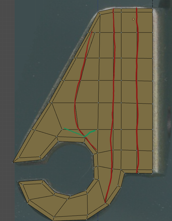
Alright so here is what I have right now. I took some idea from Deloris' example:
I have a ring of edges that goes around the entire object:
And I'm gotten close but not perfect to a goal that I made up of having the geometry flow correlate to reasonably expected directions that stress on the real world object could propagate. For example:
I'm not a metallurgist or anything but I personally would reasonably expect that if stress is applied to the tab in this direction that some major stress would more or less follow this line:
Likewise I can imagine stress on the other tab here could flow this direction in a real object:
But some of them I have muxed feelings about, for example this one:
I think the general concept on this one is right, but something still slightly off.
Now of course I realize in a real metal object there are TONS of factors that dictate how stress in one place affects the rest of the object and I certainly don't have to be perfect, but I am trying to go beyond just a model that looks good in a render and make something where the mesh topology and the real world deformation properties have a relation.
So now I have a big question - am I completely off base thinking that its at least OK to model this way when doing a technical object with a focus on theoretical/philosophical considerations over practical ones?
So I'm asking for critical feedback on this modeling idea as a concept as well as this topology considering that concept.
Thanks!
“... am I completely off base ...”
Depends ...
If it is your desire to learn modeling because you wish to be an engineer designing machines ... you need to know how stuff works.
If it is your desire to learn modeling because you wish to be an artist designing cool futuristic robots... yes ... you are completely off base.
Maybe I'm not communicating well let me try it this way:
My desire is model one single piece ever in my entire life. This clip. And I want it to be beautiful topologically without regard to how it looks rendered or used in any scene in any way. Only beautiful topology for topology's sake.
Given that - is it beautiful topology to try and approximate the way stress on the object flows through the object by looking at the way edge loops can be formed through the quads? And if one can consider that beautiful topology then does anyone have critical comments on that particular implementation?
This is both an engineering and artistic question as my desire is not to perfectly replicate physical engineering properties but to get something that is not entirely unreasonable from an engineering perspective, but that balances this with nice-to-look-at topology lines.
Seems you’re kinda interested in technical stuff ... for your information ...
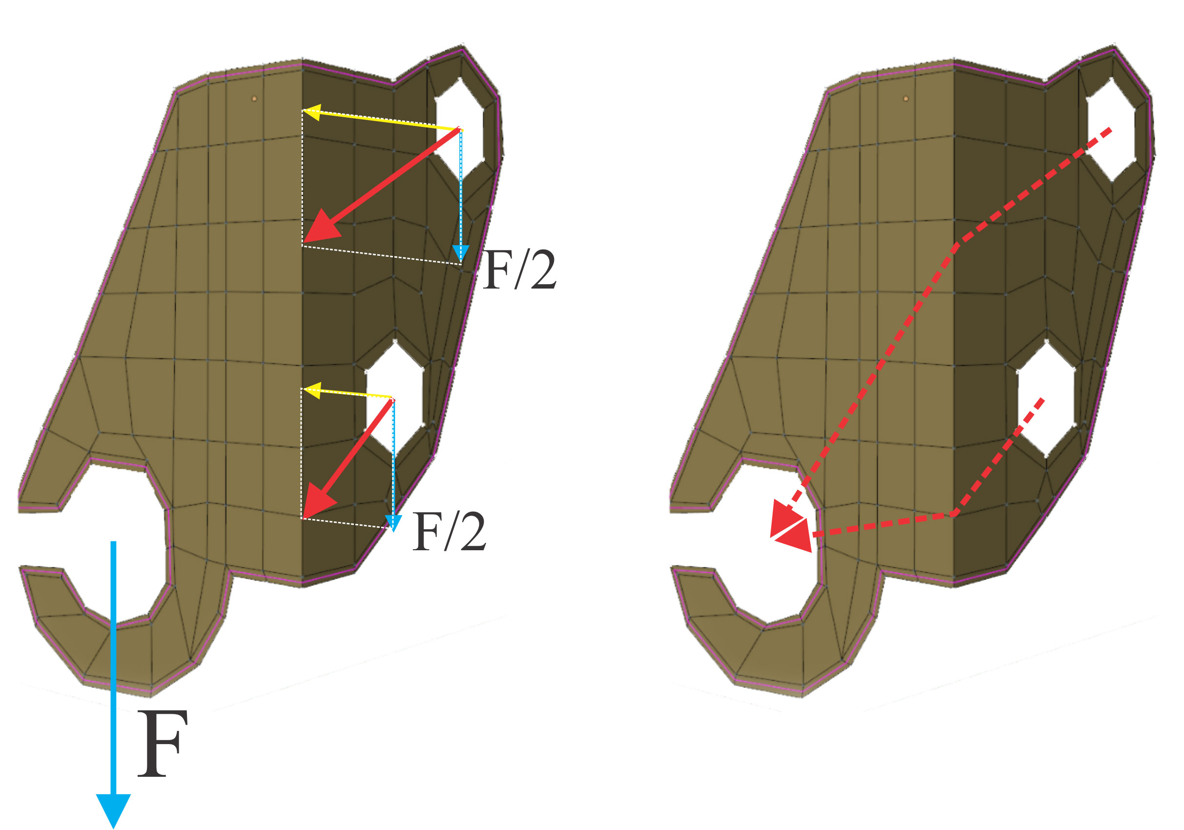
It's more complex than this, I didn’t take the third axis in account that pulls the bracket from the wall.
Or another way to say what I mean, the amount of care someone usually puts into modeling a face to ensure the lines flow according physical features - that's what I'm trying to do here but with a metal clip and not a face. I'm trying to make the choices of lines to be very intentional with a concept that "features" of an object like this is more about how it malforms under stress than things like bones or muscles found on a face. And that is what I'm seeking feedback on.
' that is what I'm seeking feedback on.'
I'm afraid you're at the wrong forum for that. Ask Google for 'engineer forums'.
If you are aiming for a cleaner topology, I would try it this way:
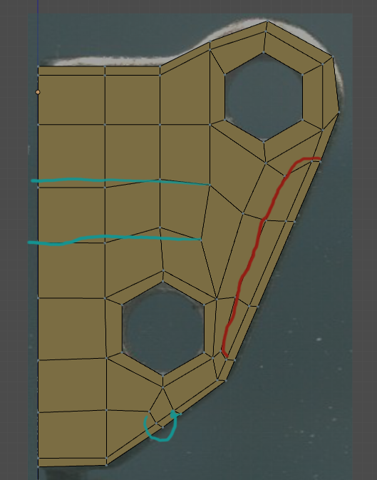
Remove the red lines/loops
The green lines indicate where you can connect that vertex that is left alone in the second image. Having Ngons can lead to issues later on, so try to avoid using more than 4 fixation points for a single polygon.
The blue lines should be straightened out and where the little circular line is you can merge those two vertices.
From a technical aspect you also need to remove the outer ring loop that you added to define a potential subdivsion modifier. Normally, you would also need to create a really high poly tube and get the ring in there using the boolean modifier, but since you said you want it to be a clean mesh, you can stick with that. Have your ring part a bit more blocky, but also not go into several thousands of polys because of a boolean modifier.
Or you start working with splines when it comes to curves.
Other than that your topology looks fine.
Thank you that is definitely is the sort of feedback I was looking for. :heart:
I definitely see what you mean on the red and green suggestions.
This one I'm curious if you can elaborate on though: "From a technical aspect you also need to remove the outer ring loop that you added to define a potential subdivsion modifier. "
I suppose from an engineering-type perspective this would not make sense to have this ring, however wouldn't such a ring be useful (if not essential) in the case of adding a subsurf modifier?
"Normally, you would also need to create a really high poly tube and get the ring in there using the boolean modifier"
Would there be an advantage to this over using a subsurf modifier on the object? I suppose it may cut down on overall geometry since the rest of the object is flat and this would add geometry only in the cut-outs and would mean I wouldn't need the ring around the outside, correct?
I'd be curious as how to connect all the points from a very high poly cutout to an otherwise low poly mesh, I'll try googling for this but if you know a resource that would be awesome!
"Or you start working with splines when it comes to curves."
I read some on this last night. I can certainly see some places this would be very useful and I will have to experiment with it!
The outer ring is not needed when you work with mechanical parts like that, because you don't use subdivision modifiers.
If you are supposed to deliver a model of a metal piece like that for a a manufacturer to work with and for example laser-cut it out of metal sheets, you would work with splines to get smooth curves.
The manufacturer gets a clean shape that he can enter into his software and his machines can start cutting that shape into metal sheets. In this case, if you want to box-model that metal piece you have to either take the fall with the blocky ring or you use the boolean modifier to create an almost perfect circle for the ring but suffer a chaotic topology around the ring part.
The difference between a high poly tube being cut into that part to create a smooth ring as opposed to using a subdivision modifier is that the subdivision modifier does that to your entire mesh and is harder to control.
While the boolean modifier will create hundreds or thousands of additional polygons as well, they will all be connected to the next-closest vertex that is available, limiting the amount of uneeded additional polygons to a fraction of what a subdiv mod would create.
You can of course control the subdiv mod too by using vertex groups but usually that will end up in a very similar result as the boolean modifier would give you.
So my advice on this would be to either take the fall with the blocky ring or use splines.
I've worked in a media agency for 4 years and one of my last clients there was a company that sold and produced mechanical parts from large to small scale, very similar to these ones.
They had a price catalogue that had every single part listed with exact descriptions, measurements, material, resistance etc. along with a technical drawing that would be similar to what you are doing right now, just without a wireframe (so all built using vector files) and a 3D rendered image.
The way we did it was we used Adobe Illustrator to create the parts using only vectors, which gave us a smooth shape with close to no hardware power required, we then imported the vector files into a 3D program like Cinema 3D or in this case Blender, made some adjustments to the vector file, gave it a thickness, smooth shading, beveling and a specific metal shader and rendered it.
Save the image, add it into the price catalogue in Indesign and rinse and repeat for 2.000 pages.
So like I said, splines if you want to get really technical, if not take the blocky ring for a clean topology.
Or use the subdiv mod and restrict it to the vertex group that is around the ring part.
Or use a Boolean Modifier with a high poly cylinder which will result in pretty much the same thing as above.
Ok I tried implementing the suggestions as best I could while maintaining quads and here is what I came up. I also made a change to get rid of a 6-pole:
This changes the flow of faces a bit but retains some of the main flows I was going for.
But I have a couple places that I'm not liking and I tried a few things but I'm not sure the best way to deal with them:
I'm sure there is some obvious answer but I don't know what it is and my trials just keep getting worse.
"So like I said, splines if you want to get really technical, if not take the blocky ring for a clean topology.
Or use the subdiv mod and restrict it to the vertex group that is around the ring part.
Or use a Boolean Modifier with a high poly cylinder which will result in pretty much the same thing as above."
Those are great suggestions, thank you - I will try those out! I like the idea of restricting subsurf to the groups around the ring, that seems like it would be the easiest to control but I guess I will find out.
I'm at work atm but tomorrow I can take a quick look at your blend file and screenshot the way I would fix it.
Working Blender on my tablet here is no fun :c
Also:
Here's one of those price catalogues that we made as PDF-file, only 240 pages, but it gets the point across. If you skip to page 30 you can see the parts with the vectors/splines in blue and then the rendered versions.
Ah yes I see, that is indeed very interesting. I've read that splines like this can be hard to work with in blender but have not tried it myself yet. Its certainly worth checking out I think.
Unfortunately it seems not possible to add subsurf to only a vertex group so I may have to try and figure out how to connect the points from a booleaned high-poly tube to the low poly model.
If you want it to get compressed, then just add keyframes to the scale! You don't need bones to squish things!
The boolean will do that itself, you don't need to do that manually.
By default it will take the closest possible vertices and create polygons out of those.
Get your low poly model, make sure you have the ring that you want to cut out "squared off" so that the cylinder doesn't go over those bounds and place the cylinder and add the boolean mod to your low poly mesh.