[edit TLDR:]
Was all going fine and then hit a wall once I added Bevel node. Why isn't it working as expected?
Bevel muted so you can see all good up to this point
When I add the bevel is doesn't matter what setting I use it stays exactly the same.Transformations applied.
Bevel unmeted: radius 0

Bevel radius 50 - no change
also the bevel only affects this one corner. Why not the others?

if I preview the bevel node I get glitchy results but it does show a different glitch for different radius values


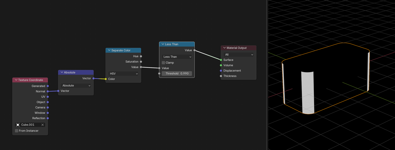
Bevel node goes into the normal input of your shader Node(Usually principle shader or the displacement of the material output Node). You have it going into the color ramp. Also Bevel node only works in Cycles renders.
I am in Cycles.
Dwayne. Bevel to Colour Ramp is exactly what Ewa does. 
Martin - values were to show that radius is having no effect that's why I used 0 and 50. And for the bevel preview radius values were just to show that the number does seem to be doing 'something'. I'm still getting the glitch effect when radius is set to .02. I don't know if the glitch is normal or not. I was just trying stuff cos I don't understand why it's not working in the way it does in the video. I'm on 4.5 but can't think this makes a difference. I can only think there's something wrong with my model but can't think what when scale and rotation applied and I've checked normal orientation. I'll do a test on a brand new beveled model and see what happens

Works fine on a different model so must be something to do with my model but no idea what. Any ideas for what I can further check?
Hi Charles,
I haven't taken this Course yet. This is a highly unusual way to use a Bevel Node, but then again, everything is alowed, when it gives you the effect you want.
But as to what could be wrong with your model..'.double Vertices' come to mind. Maybe interior Faces.
If you can't figure it out, you could post a link to your .blend file here, so we can see if we can find what's wrong with your camera.
Martin. I went through the mesh with a fine tooth comb. After a wild goose chase trying to join vertices of the inner extruded edges I rewatched 1.2 BlockOut lesson are realised the mesh is supposed to be separate!
However I did find a few edges marked sharp and clearing those and replacing with a bevel weight has allowed the bevel node to work in the sense that different values now produce different results.
However it doesn't feel like a good result. It's supposed to suggest wear but all it seems to do to my eyes is accentuate the low poly mesh and produce highly unrealistic 'wear' on sharp vertical lines on an object that looks smooth.

Upping the samples only highlights the issue

At least I got to the bottom of it but it's taken a day to do so :(
Well,
This is the way Ewa did the Shading, but it's not the only way to get a good result.
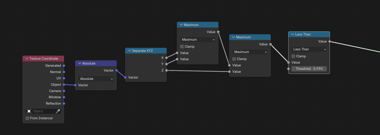
For instance, here's a fun 'corner Mask' for a situation like this:
The Normals in the Cardinal directions are 1 or -1. The rounded corners have RGB values, all Absolutely less than 1, and the Value of a Color is the Maximum of RGB, so if the Value is Less than 1, the Normal is not in a Cardinal direction.
Ordinarily, the Value of a Color is utterly useless, so it's fun, that we can use it to our advantage here.
Combine this with the rest of the techniques instead of the Bevel Node if you feel adventurous. You can always improve on some of the techniques taught in a Tutorial; it is a great base to work from. If you had to do this all from scratch without the Course, it would be extremely difficult.
Thank you. I can see what it does but I'm really sorry as I don't understand at all .
So just to step through what I do/don't understand
My solution was just UV unwrapping it and painting on the wear I can use as a texture mask. That seems like the best way any wear can be made somewhat real and natural. Obviously a bit more involved but it's super easy to unwrap.
Hi Charles,
RGB Values in Blender are between 0 and 1. (Which makes a lot more sense than seeing them as 8-bit values (or even worse, writing those 8 bit values as hexadecimals) and makes calculations a lso a lot easier (for instance 1 times 1 is 1, as opposed to 255 times 255 is 255, but I digress.))
Normals are between -1 and 1 (because they are normalized) in blender, If a Normal is 'facing' in the (Object's Local) positive X-Axis, that means it is the Vector (1, 0, 0).if it is facing in the negative Y-Axis, it is the Vector (0, -1, 0) and so on. The Absolute Value of the Normals that are (anti-)paralel to the (Local) X, Y and Z Axes are (1, 0, 0), (0, 1, 0) and (0, 0, 1). These Vectors can also be read as RGB Values!
Any Normal Vector that is not aligned with one the 'cardinal directions', can be written as (x, y, z), where the absolute value of each of the x, y and z is necessarilty smaller than 1 (because the Normals are normalized), so the maximum of the 3 (x, y and z) is also less than 1.
"Why do you need colour at all - why can't you just plug absolute into the Math node?"
Because the Color can be Separated into HSV and the Value in HSV is the maximum value of R, G and B. So we could also have done something like this:
And yes, you are right, Unwrapping and Painting a Mask is a great way to do this. There are always multiple solutions.
Think it's good to know how the Procedural Mask I made works; if nothing else you learned that Blender is not Photoshop and RGB Values are between 0 and 1.
Oops forgot a question...
"Is the models colour being turned into white AND black or just one of those? I ask cos it's only passing through values of less than 0.99 so where's the info to turn something white and black?"
The Less than returns 1 (pure white) if it's True and 0 (pure black) if it's False.
Wow... thanks for all this. Yes I had NO IDEA that RGB values could be between 0 and 1. And I see it's been hiding in plain sight. Have never noticed until now!

So this does make more sense now. However i don't see how "... opposed to 255 times 255 is 255"
255*255=65,025. No?
And this "Because the Color can be Separated into HSV and the Value in HSV is the maximum value of R, G and B. "
So in the example above it compares 0.486, 0.008 & 0.494 and returns 0.494 (the maximum value of the 3) and as that is less than 1 it then turns it white?
Presumably 0.486, 0.008 & 0.494 are not from the RGB but from the normal and then used to turn the model white or black with the separate colour node
In your 2nd screenshot did you make a mistake with the texture co-ordinate as Object not Normal is plugged into the Absolute node
It's mind boggling how you know all this! I know this is probably simple stuff but it makes my head spin. It's so much easier when you can just look at stuff and evaluate it!
"255*255=65,025. No?"
In normal math, yes, but when you say, that pure red would be written as RGB (255, 0, 0), then pure red multiplied by pure white (for instance) would be (255*255, 0*255, 0*255), resu;lting in (255, 0, 0). This was just meant to show that having the RGB values going from 0 to 255 really messes up the math.
"In your 2nd screenshot did you make a mistake with the texture co-ordinate as Object not Normal is plugged into the Absolute node."
Indeed, I made a mistake there (i am just so used to using Object Coordinates), that should be the Normal Coordinates.
You'll get used to this over time....or not, but that's also not bad, there are many great 3D artists, that don't have any (or just very little) theoretical knowledge. That doesn't stop them.
Just additional information: The color of the axis in blender correspond to the color channel. This was done on purpose. So XYZ = RGB. X axis is Red, Y axis is Green, and Z axis is Blue. Under the hood color in blender is HSL 32bit float. This is a factor output to RGB(In the RGB color picker). A factor is a percentage represented as a whole number. 0.0 is 0%, 0.5 is 50%, and 1.0 is 100%. The 0 to 255 is actually binary converted to decimal. The math is actually binary math and way more advanced than any nonprogramming artist needs to know. Note: Blender uses the base gamma for it's factor, because of this you can actually have output values that are higher and lower than the 0-1. Blender will adjust the monitor's gamma AKA Gamma correction. This information can get lost during rendering depending on the file type and color space used. That is why on nodes, like the math node, have a clamp check box. This keeps the value between the 0 to 1.
Thank you. I had no idea about xyz colours but this now explains the colours you see from texture coordinate node