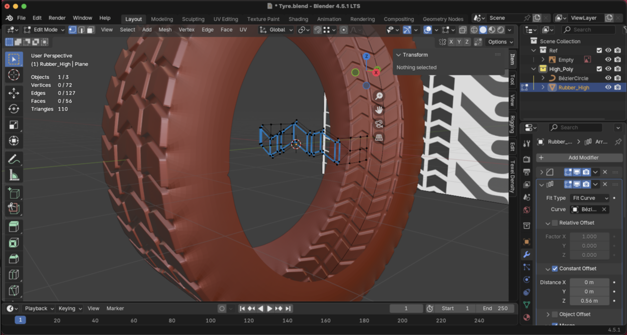
Hi, even before you got to the difficult part. I just encounter this issue. Attached in first image. Then it did sort of fix it that tip of yours but created funny mesh. It's not looking like yours. Must be a way to create this so it's flash and when applying not having to deal with all this fixing. Let me know if there is something that I can improve to get it close to your one. Or is there a different way to make this exact? Thank you.
Hi Sergio SSergio4624 ,
What you can try, is to use a Simple Deform Modifier, instead of the Curve Modifier, then you can close the gap by increasing the degrees to above 360 (type in a number greater than 360, for instance 361, to disable the soft limit, then you can slide it till it fits);

That's how I like to do it, maybe you also find it easier to control.
If the edge of the profile would be straight, you could use exactly 360°.
Hey there!
One method would certainly be to try out what Martin has done in the post above, I think that's very clean way to do it with less fiddling around and having to troubleshoot small issues!
If you wish to continue the way the tutorial is covering it, I believe the reason you are getting that little indentation in the first image is because the first and last instances in the Array are not merging. There may be too much overlap, thus making the distance between those vertices too far for the modifier to catch them and merge. My suggestion would be to try increasing the "Merge Distance" option on the Array modifier, while also making sure that "First and Last Copies" are enabled. You likely will only need a really small value, something larger may end up merging the entire model into itself. :)

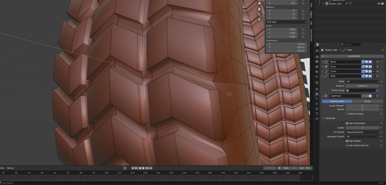
I think your problem here is that the two vertices pointed to in blue are not aligned with the ones pointed to in green. So when they merge you get that indent in the tire.

That section should look like this:
Also,
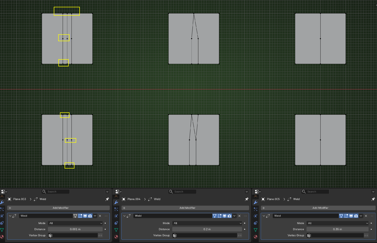
Bear in mind, that Merge By Distance and the Weld Modifier are meant for when Vertices are already (almost) on top of each other.
Otherwise, the behavior might be unexpected and almost certainly unwanted.
Here is a simple example; top row used Merge By Distance and the bottom row the Weld Modifier (both with the same Values):
When you have more complicated Meshes (which will be almost always the case), the chaotic behavior can (and often wil)l result in horrible messes.