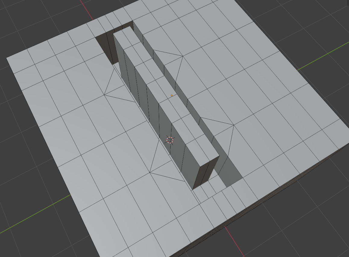
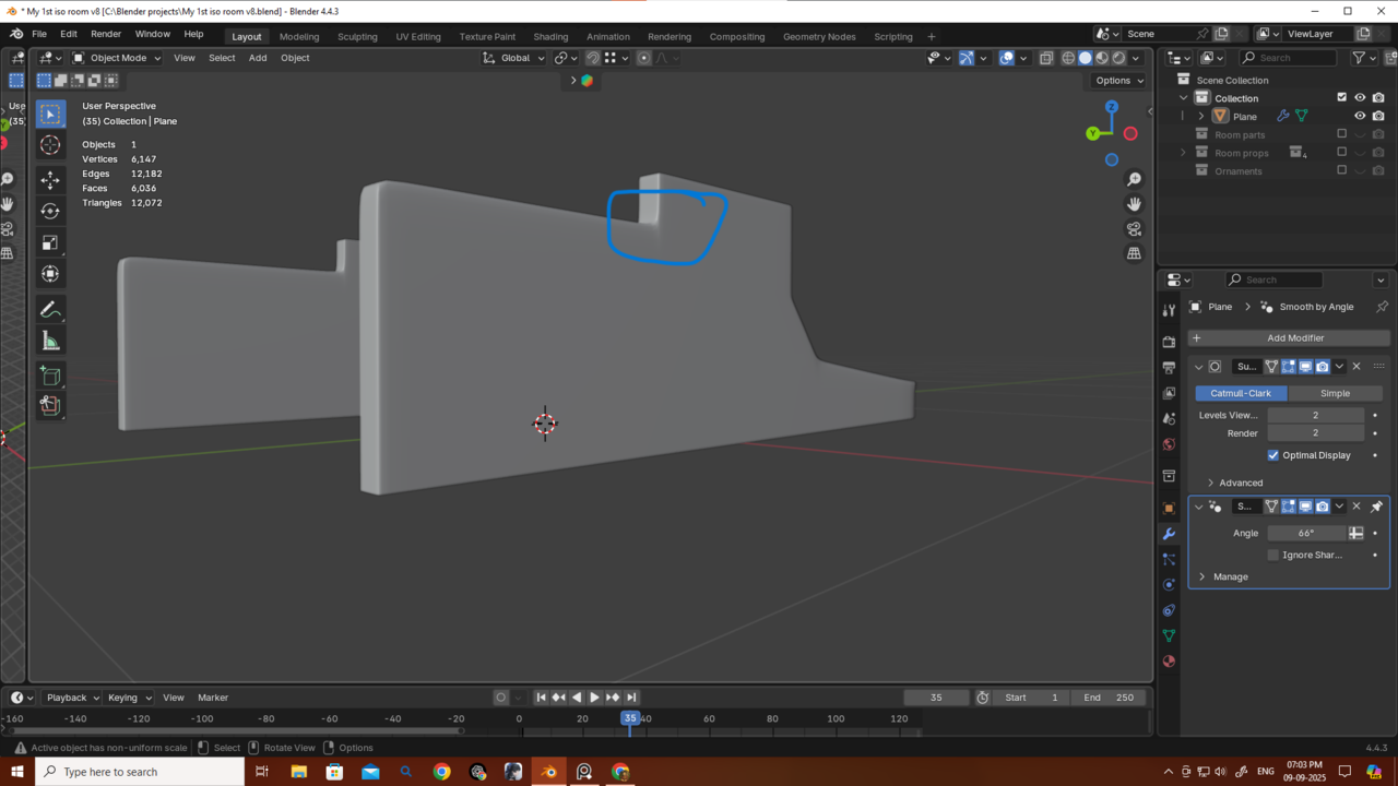
So I’m sharing my topology along with the object part I’m trying to create. There’s definitely a better topology than mine — but what would it be, and how should I make it? I sometimes really struggle with finding better topology. I know the theory of how to control my loops, but when it comes to actually applying and managing my loops and poles, I get stuck. Here’s the part I’m trying to create and my topo.


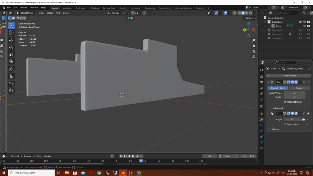
 Also is there any way to actually avoid this type of poles cause this causing this pinching issue.
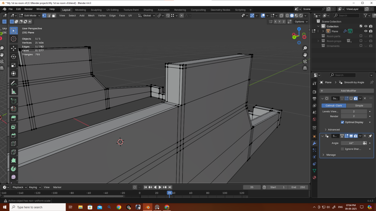
Hi Deb,
Topology is always a bit of a puzzle. There is also not 1 way of doing things.
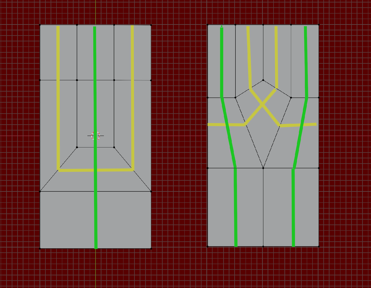
Now, it looks like you are going for subdiv modeling. What I like to do is to start as simple as possible, let the Subdivision Modifier do most of the work and only add some Loops to guide it. And then add holding Edges where needed.
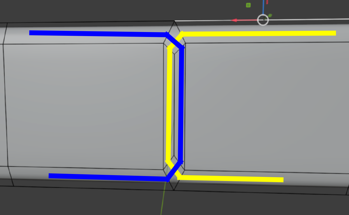
Also, try to even things out, for instance:
For an Edge Loop along the top all around, you might be able to use Inset.
I can clearly see the difference in our topology. I didn’t model this by putting a background reference image and adjusting vertices that way. Instead, I started with a plane, extruded, and so on. So, does that mean my method isn’t good for subdivision modeling? Do I always need to start modeling like you when I’m trying to do subdivision modeling? Is that why I’m getting the pinching? Also, is there no way to avoid that pole in the corner I mentioned?
And Martin, do you consider my topology for this very bad?
Thank you very much, Martin.
Thank you very much omar..but this will create a traingle so how to fix that ? If I subdivided one edge then the next wil became an ngon and so on..so what's the trick here?
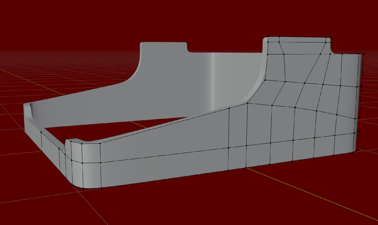
I started with a Plane without a Face, Beveled the Corners and the Extruded up a bit. The made some loop cuts, so I could extru part of the Mesh up further and then did that again. And again...,etc.
The point is, just try something out and if it doesn't work, start (partially) over.
What you did 'wrong', is that you started too complicated in 3 dimensions, which gives you too many Vertices too handle. I basically just have a 2 dimensional surface, that is bent, which is much easier (and a Mirror Modifier also makes your life a lot easier).
But let me say it again, there is not just 1 way that gives a good result.
At some point, you will look at an object in real life and 'see' the wireframe of the Topology...of any object...and person or animal. But even then, you usually won't get the Topology of your model 'right' in 1 go.
Trying out different things and see what works and what doesn't. And have fun doing that.
That trick is to use sparingly, only on flat surfaces that don't deform. You can leave the triangles it creates there, since they wont cause a problem is the surface is flat. In the end we must choose, or too many loops going all around creating tons of unnecessary geometry, or a triangle or two. You can also convert the triangle into a diamond quad junction like Martin did.
Thank you so much, Martin and Omar — I really can’t describe how grateful I am. I tried working with a simple 2D plane just like you suggested, Martin, and wow… it was so much easier to work with! It only took me 2–3 minutes to create the shape, whereas my first method was so clunky.
But I still ran into some confusion, and I’d love for you guys to take a look.
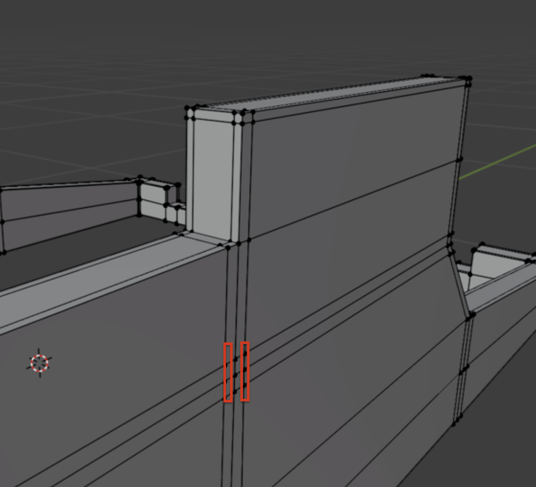
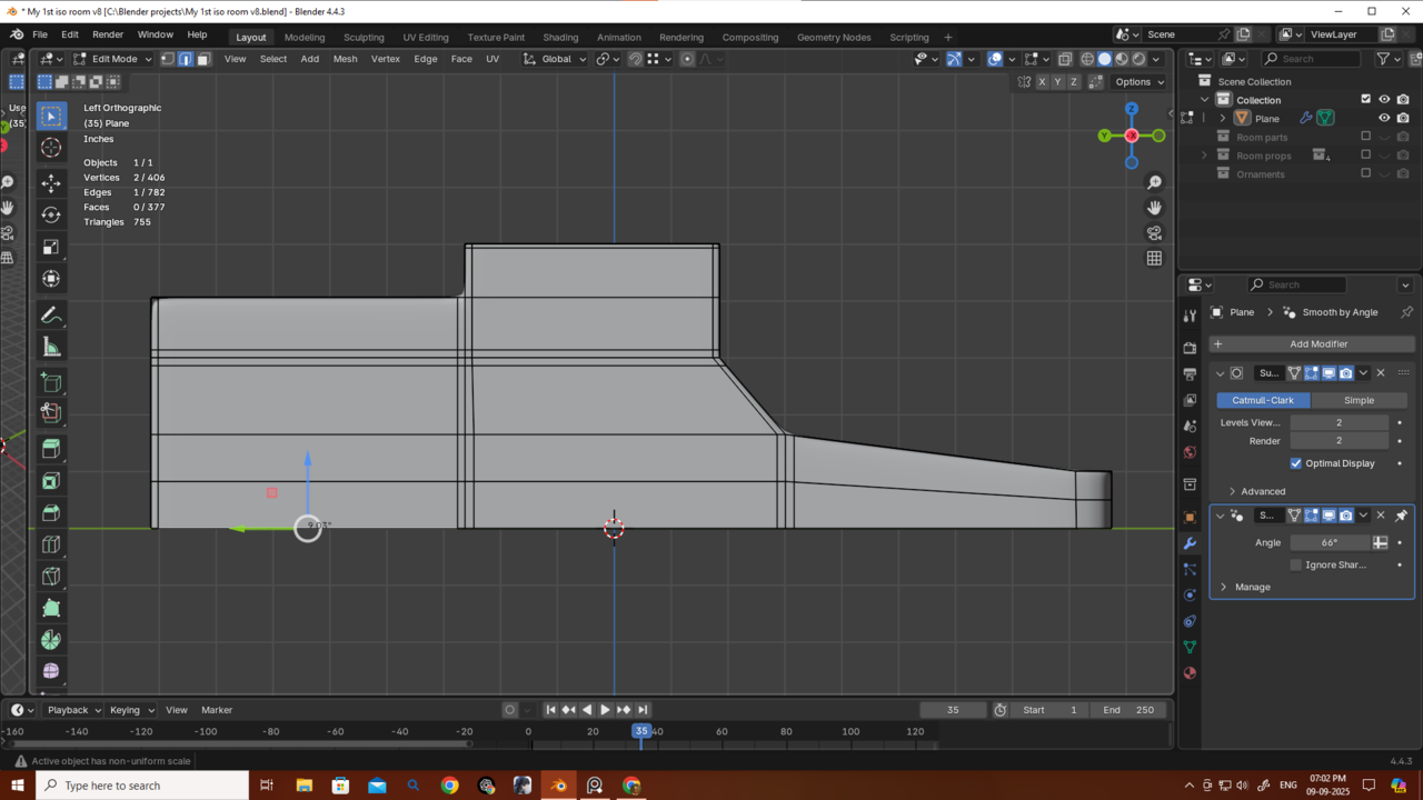
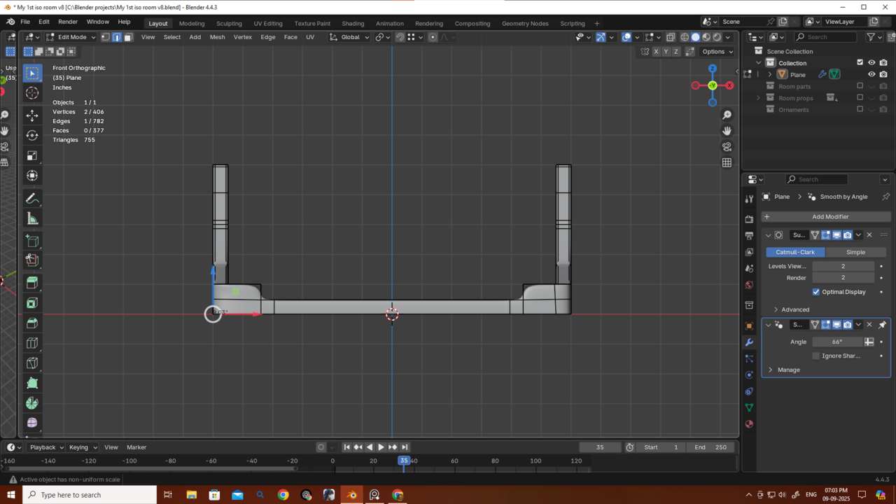
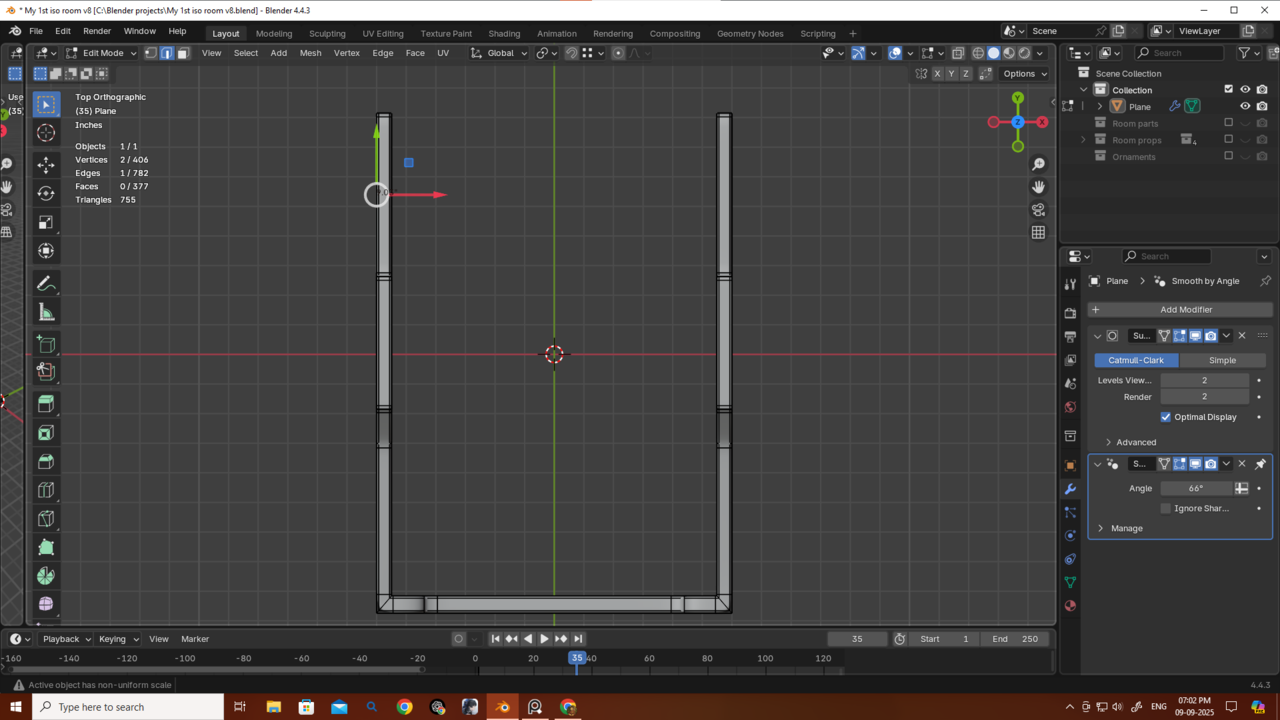
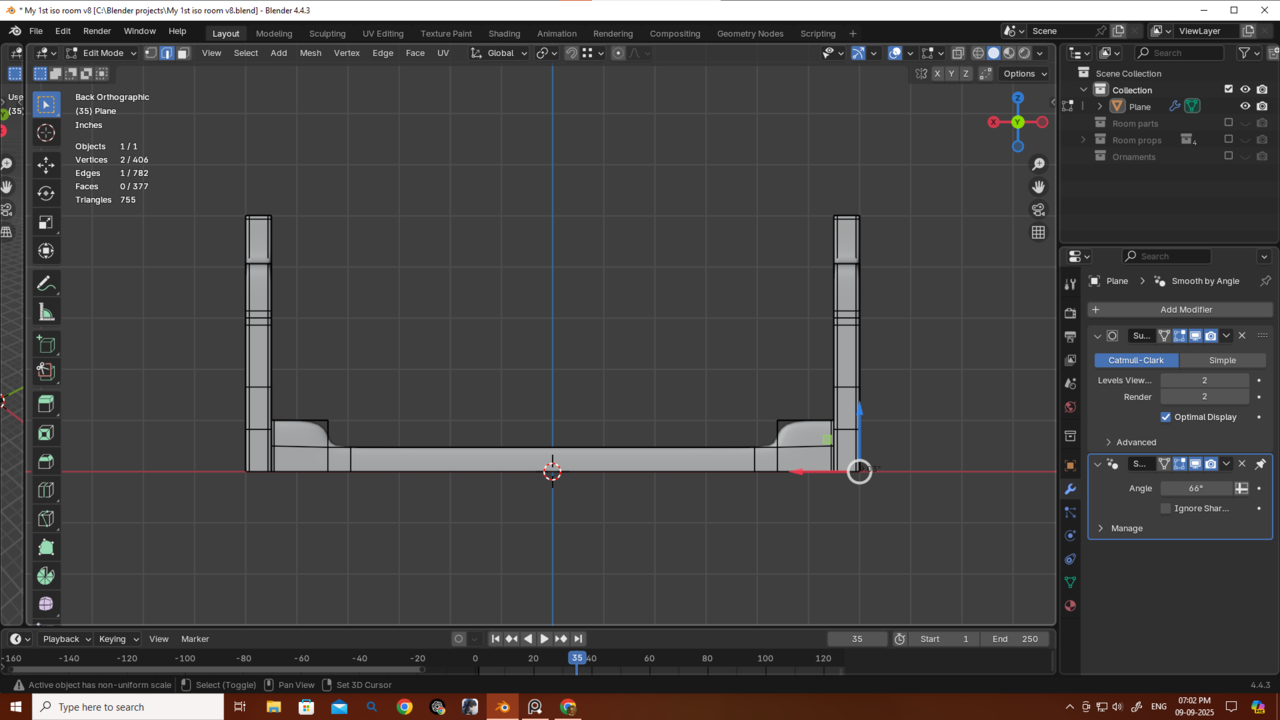
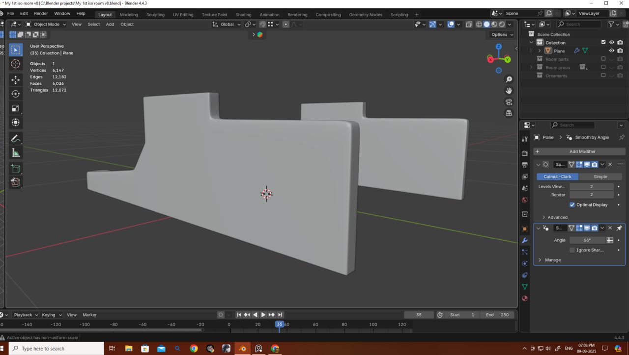
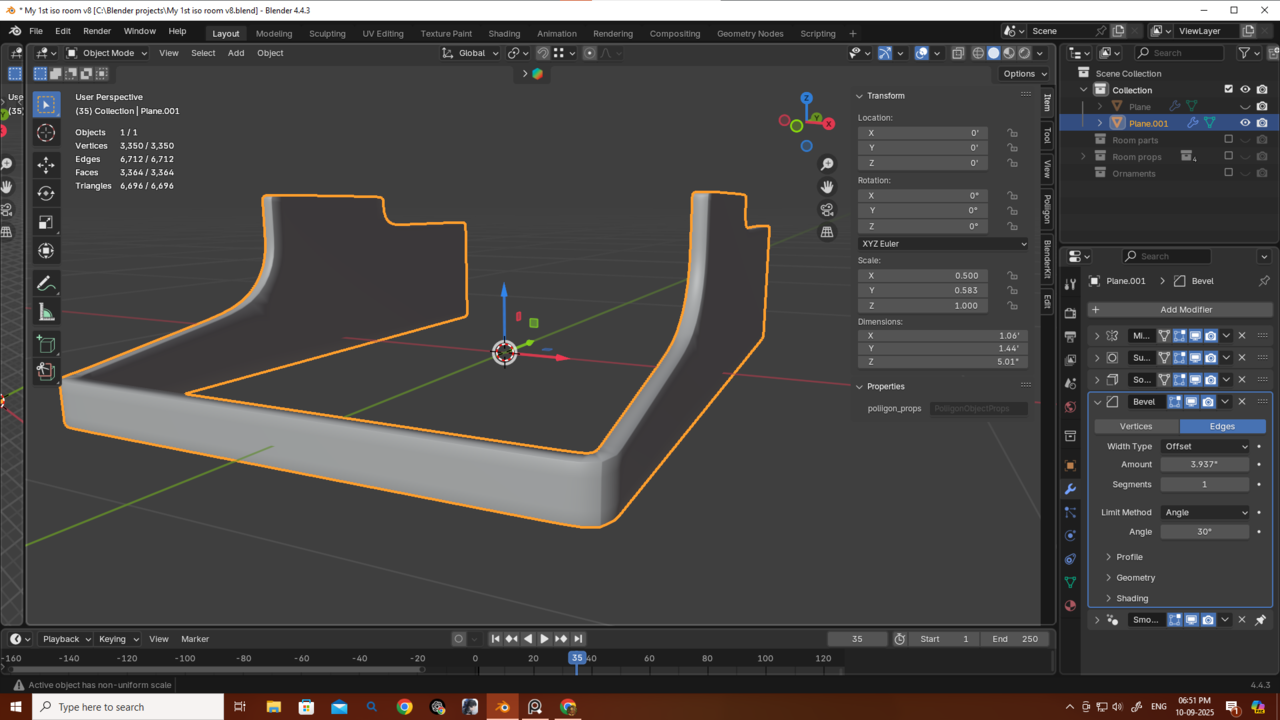
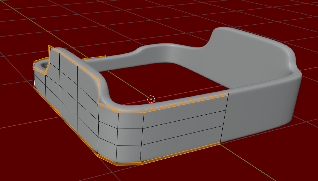
First of all, here’s my topology for this new model. I had to add two extra edges at the end to give the shape some sharpness and make the mesh follow the form. Should I have just used crease on those edges instead? Which would be better?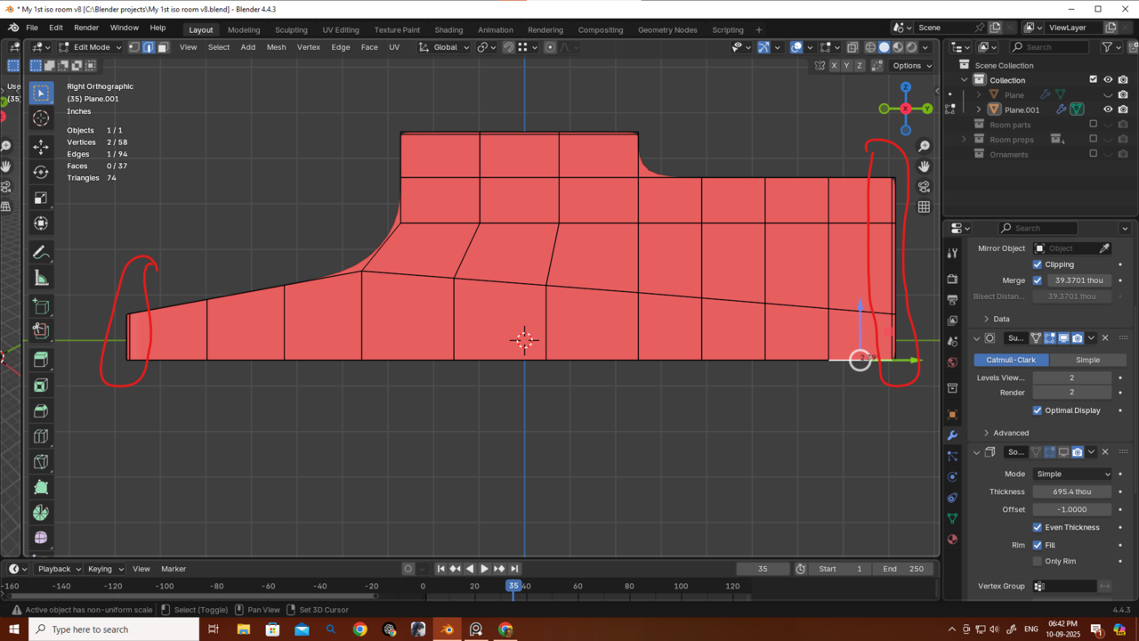
Also, as you can see, the edges are very sharp. When I add a Bevel modifier, it doesn’t really work — even if I move it above the Subdivision modifier, it still won’t smooth out the sharp edges. Is this happening because I started with a single plane? I’m not sure what to do now or how to get rid of these sharp edges. Also i am getting way too much poly count if i add a bavel modifier.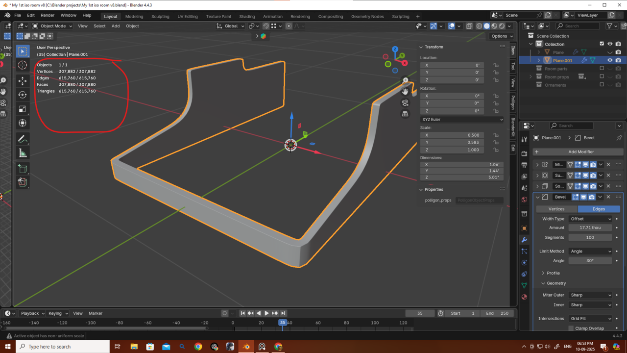
Thanks as always — I really appreciate the hard work you guys put in for all of us.
Hi Deb,
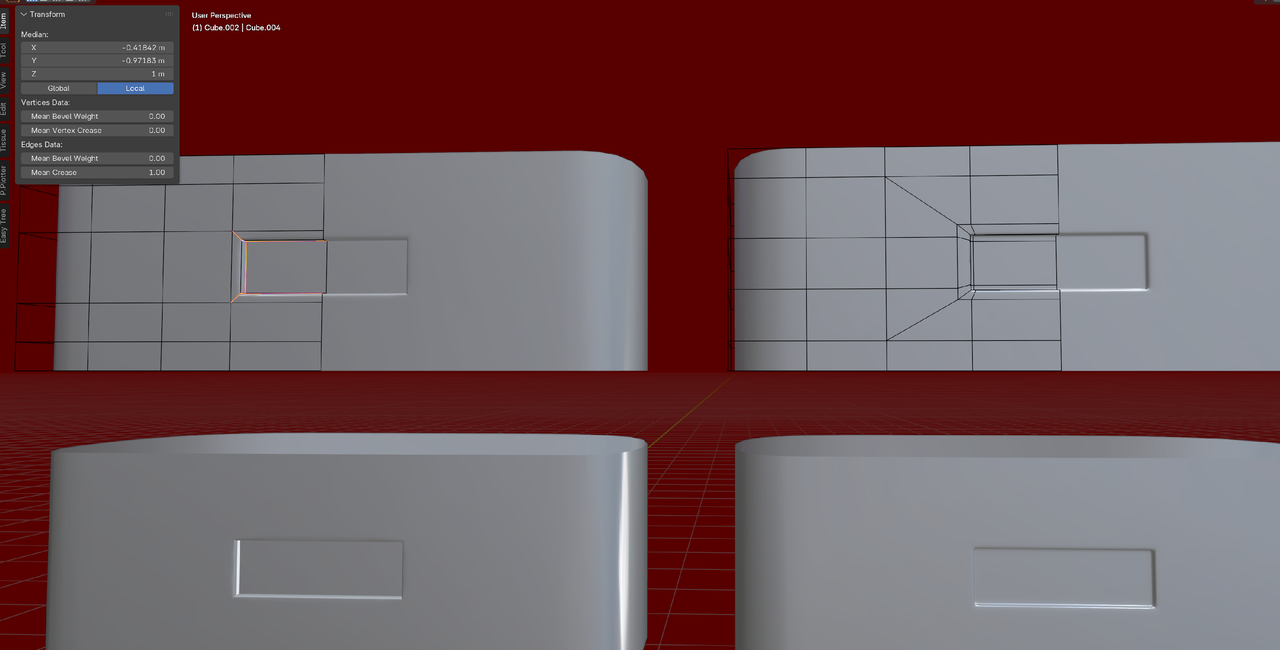
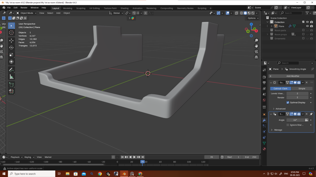
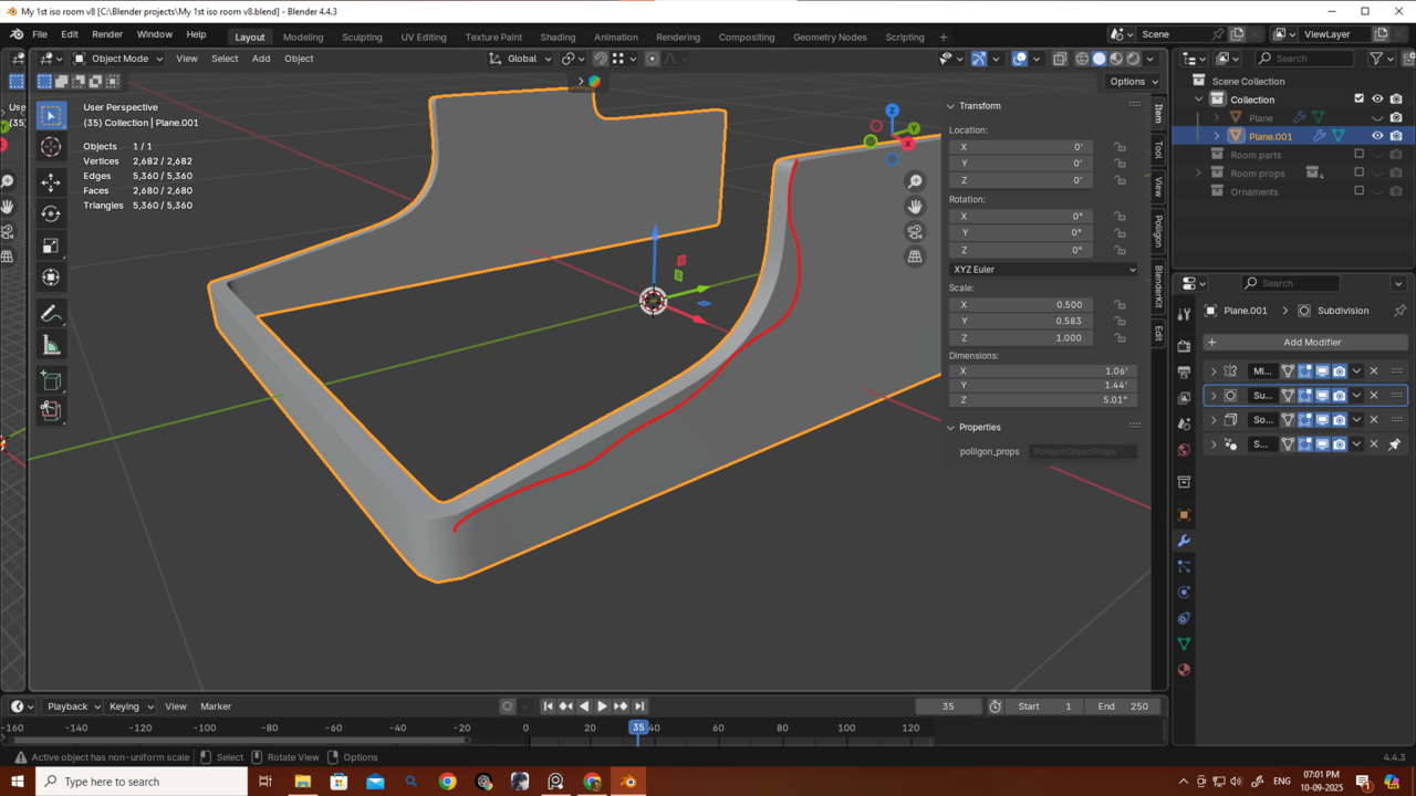
What I would try, is with that shape youve got, use an Inset on the whole Mesh to get holding Edge Loops all around the top and bottom. Then you can remove your Bevel Modifier and let the Subdiv Modifier round out those sharp edges. The order should be Mirror, Solidify, Subdiv (and the Smooth By Angle).
So you get something like this (make sure that you have Clipping enabled in the Mirror Modifier, before Insetting, or Apply the Mirror, and re-Add one again after the Inset):
Don't look at the Topology in this one, this is just a demonstration of the Edge Loops.
I was really waiting for a reply — thank you as always, Martin! This is looking so so much cleaner and good now.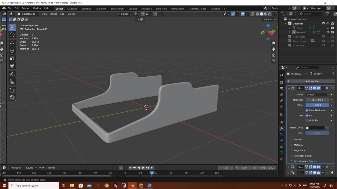
Okay, I get it now… sometimes I just blank out and forget simple things.
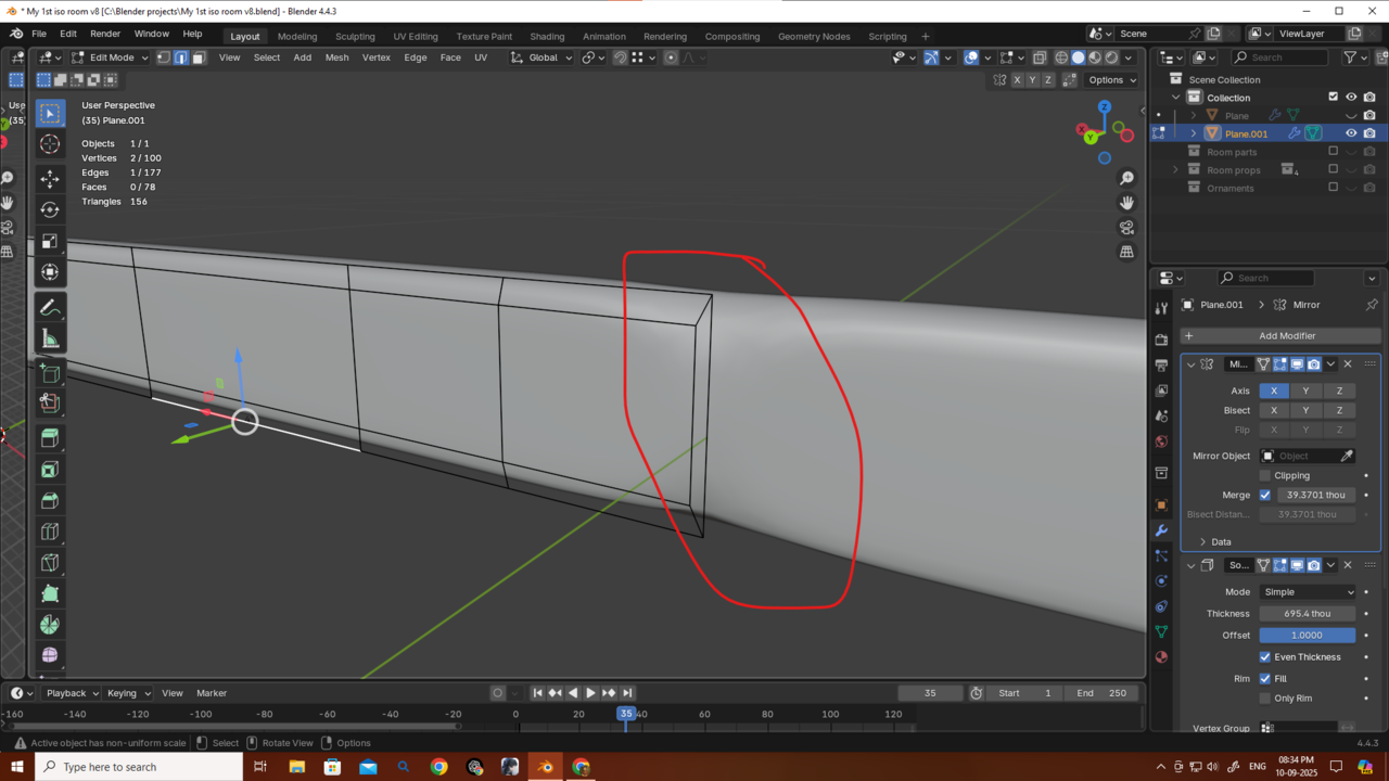
So basically, we’re mirroring the part, then adding thickness with Solidify (which creates another edge), and after adding Subdivision we’re just smoothing between those edges — kind of like a bevel, but without creating unnecessary polygons.
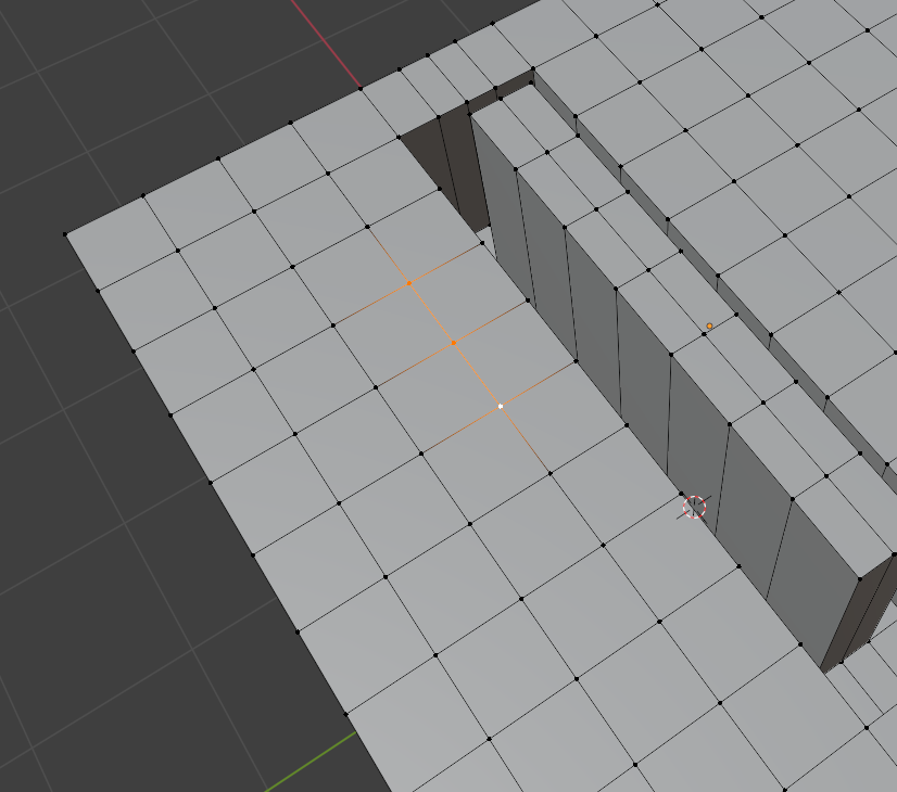
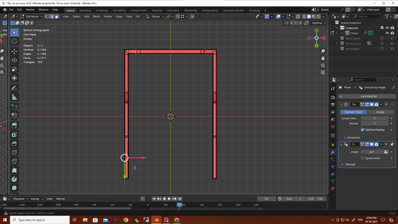
But I’m running into this issue.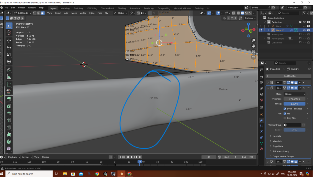
I tried fixing it this way: after applying the Mirror modifier, I added two vertices, connected them, and created a diamond-shaped quad as u yesterday told me — which fixed the issue.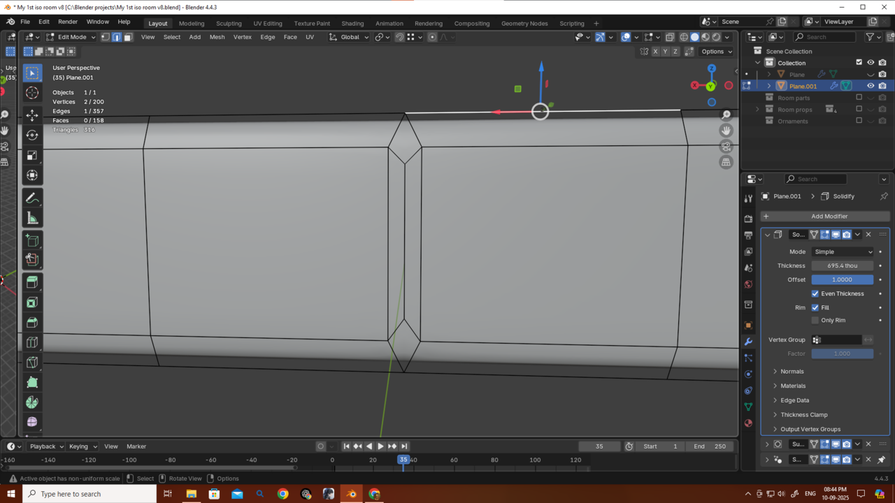
Another way I tried was just merging and deleting unnecessary vertices, which also solved the issue and avoided those extra polys. (Thanks for reminding me about that yesterday, Omar — I really forget stuff sometimes.)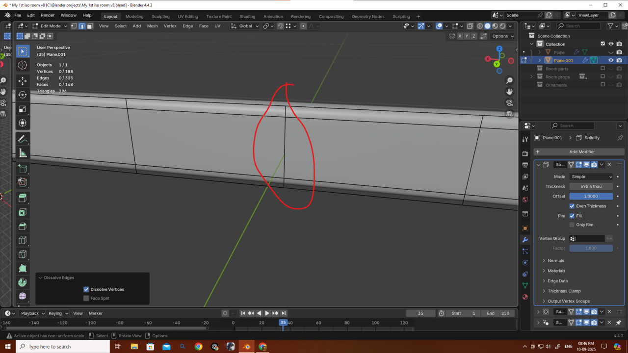
But is there any other, more optimized way to solve this? (Something cleaner than these manual fixes, even though it’s not exactly hard manual labor.)
Thanks as always, guys! Without you guys and this community it would have been so much tuffer.
Hi Deb, Applying the Mirror Modifier and then Insetting and the re-Adding the Mirror is the easiest, foolproof way.
Having the Clipping enabled in the mirror, should also work, but you'd need to disable Boundary in the Inset (so I, B) and you can't do that in this case, because the top and bottom are also Boundaries...(I forgot about that, sorry).
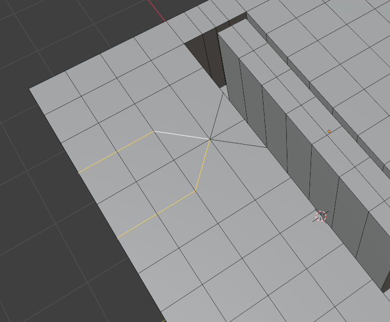
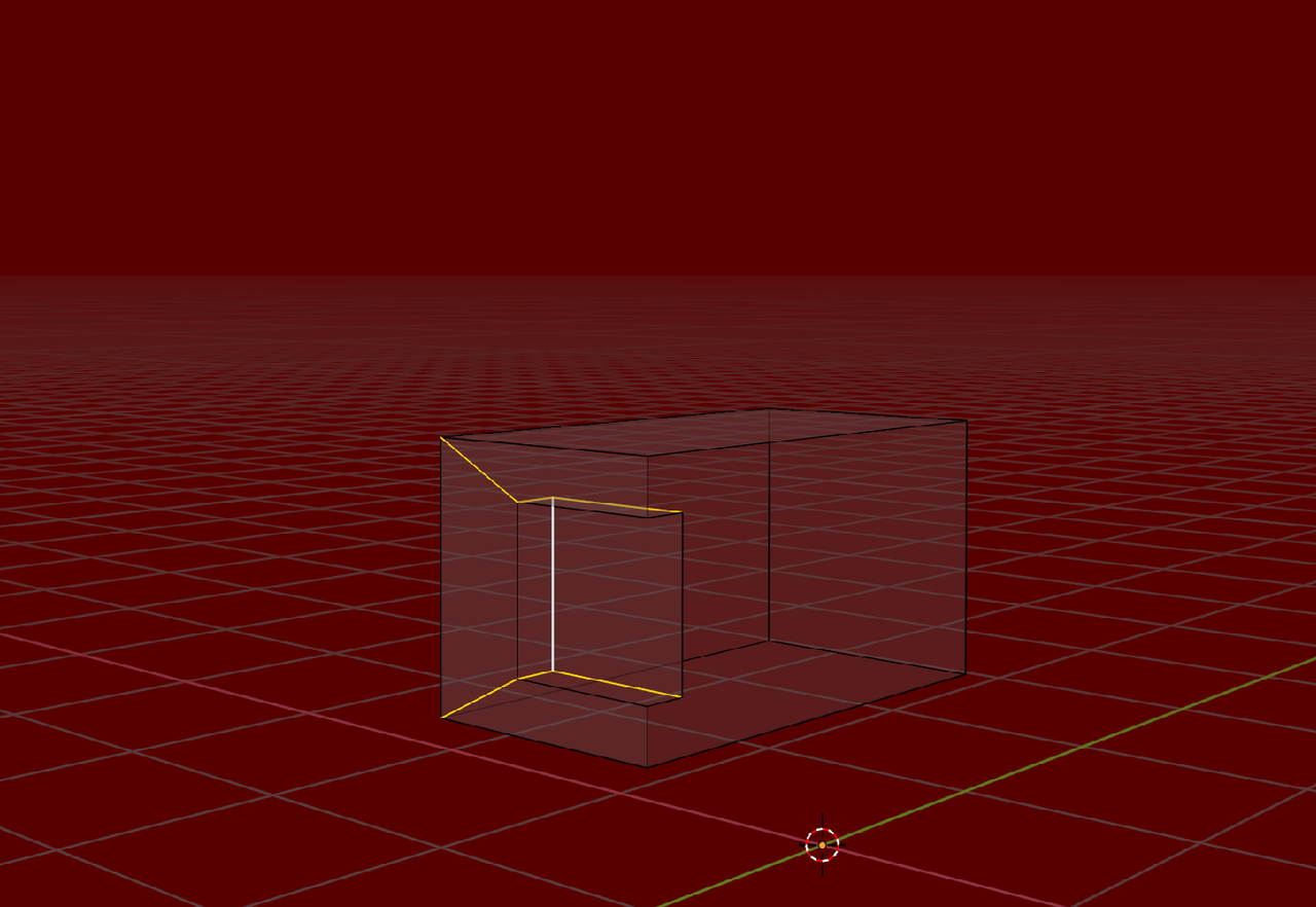
You solution with the diamonds isn't good, because it ruins the Edge flow:
Thanks as always, Martin.
I understand now why it was bad, so I merged the verts and also deleted the extra edge loops that were causing the uneven spacing — now there’s no issue.
Thank you very much, Martin.
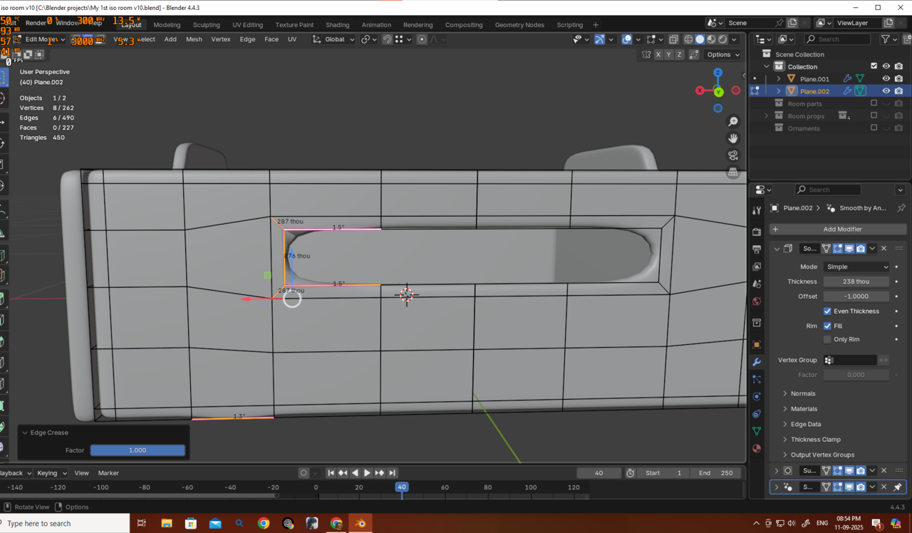
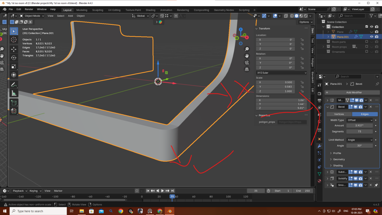
I also tried your method here too, and it looks fine as well. But as I asked before, what should I do in situations like this where I want the mesh to look more “squary” in that spot?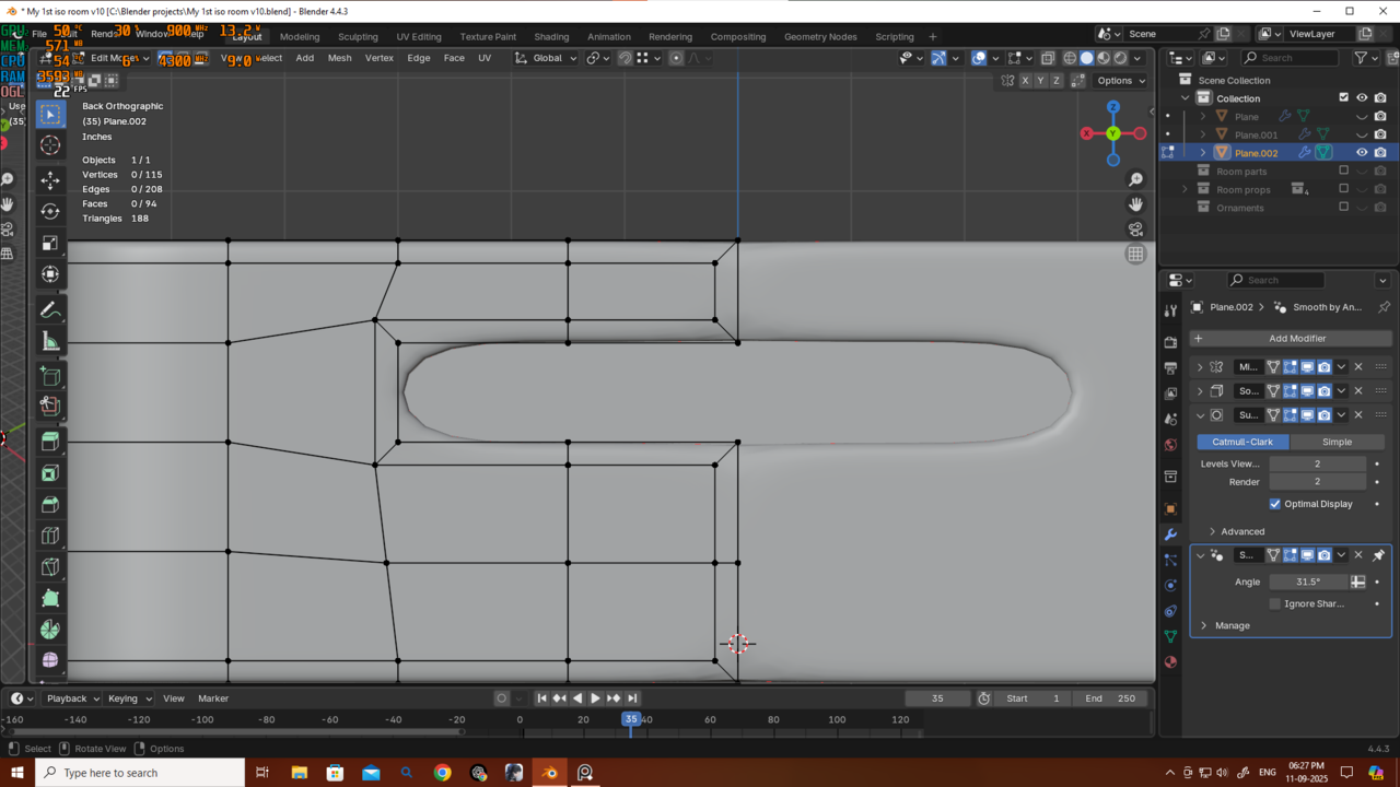
Should I just add new edge loops to guide the mesh that way, or is there a better method for handling this?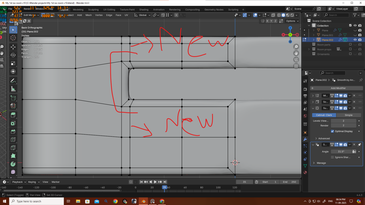
Thanks again!
Thank u martin.
But why my edge creasing is not working properly?