Would I set it up like this tank track tutorial?
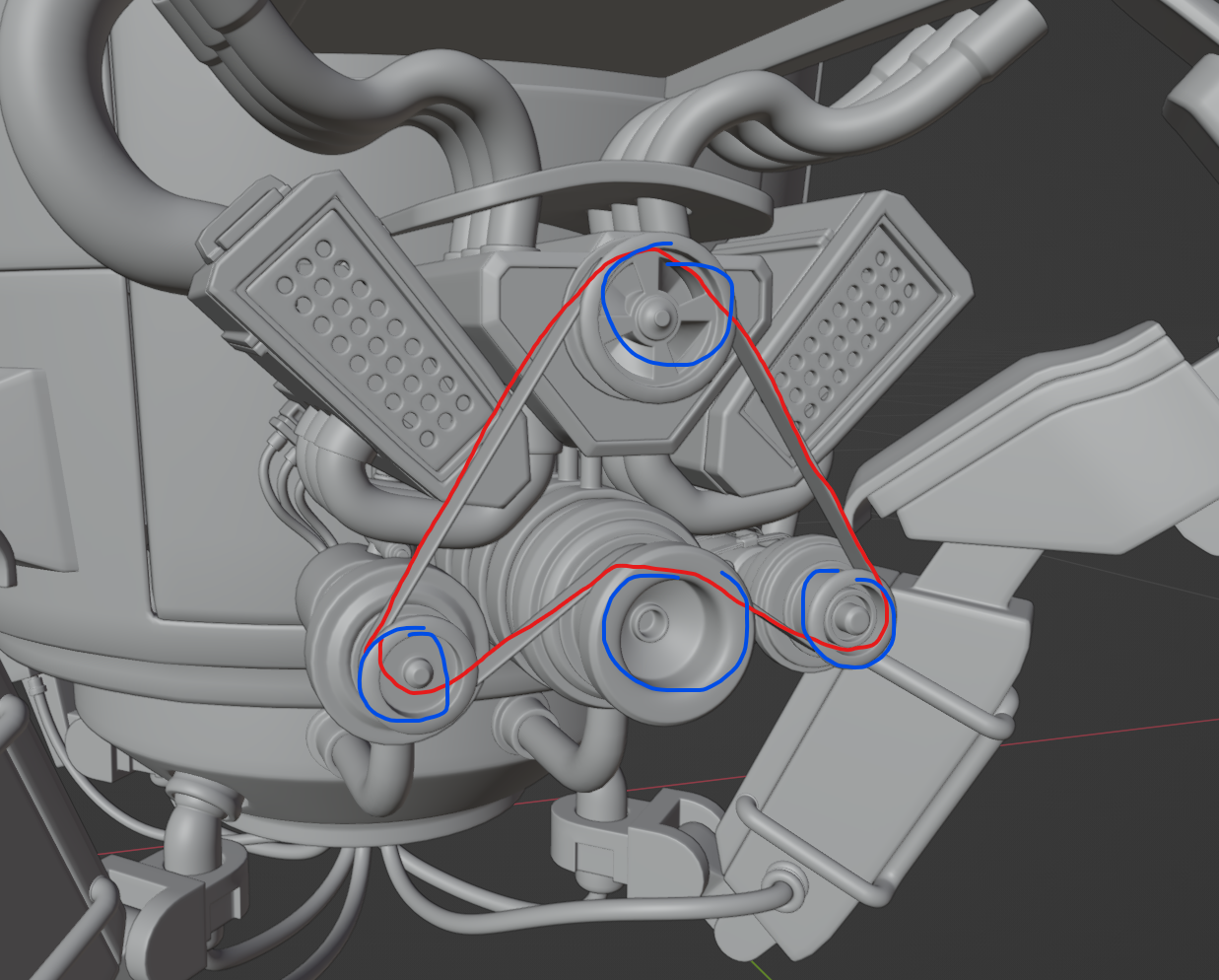
I imagine I could set up a chain of bones along a curve, weight paint the belt mesh to the corresponding bones, and set up a few constraints and drivers so they follow the curve when the motor engines rotate? I also imagine I could probably confine a driver to a displacement modifier (vertex grouped to the parts of the curve that are between the motors) to cause the curve to wobble ever so slightly?
I've just switched Blender off for the day so I'll have a crack tomorrow! But boy am I keen to work out how to make things work!
Hang on, I can't add a displacement modifier to a curve. What else could I do to make it wobble in certain spots?
You don't necessarily need to animate the belt, only loop the texture to give the illusion of the belt rotating.
You could use a noise modifier in the graph editor if you want to add some wobble, you only need add a duplicate keyframe at the start and end of the timeline to add the modifier. You may want to consider wobble on the engine itself.
My first thought is a curve to use as a path. Then use hooks to bones of an Armature for the wobble. You can use empties, but then you have to manage all those actions if you later decide to expand your animation. Then use follow path constraint on belt mesh point it to the curve and check follow and offset. With offset you have a 0.00 to 1.00 range 0 being start of curve and 1 being the end of the curve. I personally would setup a driver using a bone, because I like to keep as much of the animation data attached to a rig.
Sorry to flood your post, but I just thought of an even easier way to setup a control bone. Instead of using offset(so uncheck that on the follow path constraint) use the time evaluation. By default the evaluation is 0 to 100. Click the curve/path then under curve/data tab of the properties editor under the path panel change time from 100 to 359. That way it goes from 0(start of curve) to 359(end of curve). Then in your driver you can use:
degrees(var)%360
Where var would be the axis(X, Y, or Z) rotation of the control/driving bone.
Thanks guys! And Dwayne I encourage you to flood my posts, I really appreciate you providing all your knowledge whenever I ask something! I'll have a crack at your tips if I get a moment this evening!
![]() dillenbata3 I haven't gotten to this yet, I'll refer back to your ideas when I do! I'll keep working the leg setups for the time being.
dillenbata3 I haven't gotten to this yet, I'll refer back to your ideas when I do! I'll keep working the leg setups for the time being.
I had another thought in regards to this though. I'm just watching through some of the videos in the offroad course. What I thought would be cool would be to set up something so I could essentially turn the engine on and have it stay perpetually on. The motors would spin, and the belt would loop around (with a little bit of wobble), and the engine itself would have a subtle gitter while it's in an idle state. Then as the legs start to move, I could increase the engine speed.
I'm just thinking aloud, but would I be better off setting up a custom property with a driver to manually adjust the engine speed (and all it's related components) as I see fit? Or would there be a way to use the animation of the legs to drive the speed? - This option might be too intense for my current knowledge of rigging, so for the time being I'll probably go with the first idea.
Or, I animate the speed in the graph editor itself rather than restricting it to a custom property (I'm guessing the graph editor will give the animator (me) more freedom).
Again, just throwing ideas around, but is there a way to set something like this up? IE the engine speed varies by how much the legs are moving. Or is this a similar situation where I am likely to be over complicating things like in my IK properties question? It's also probable that the engine's animation isn't going to visible at all times anyway.
I mentioned this to Wayne recently, but I think rigging might be where I'm having the most fun, and I'd like to push myself with it. I'm going to assume I'll have a good time with animating - and those two go hand-in-hand - so I appreciate you lending your thoughts!
The answer is yes. As for overcomplicating it, I don't think you are this time. This is making animating the engine easier for the animator(yourself). I would go a different route. Use a bone as the single controller for engine running. It would drive and action constraint. Then just speed up or slowdown the bone's rotation to speed up or slowdown the engine. I'd also have separate controllers for wobble and engine shake. That gives more freedom and allows to add character to the engine.
Animation and rigging are different creatures that work together. Kind of like modeling and texturing. I love rigging. So in terms of workflow rigging is more rewarding and you have to do a lot of problem solving. Animation is more soul sucking and experimentation. In terms of output or results, rigging is kind of an all at once reward which can be very underwhelming. Animation has lots of check points with satisfying visual feedback. Plus it's what other people see and praise.
Adjusting speed based on leg movement would require a lot of figuring out the mathematics then figuring out how to setup movement sensors or at least faking it. Can it be done? The answer is yes. The real question is it worth it to you? In a production the answer would be no. One it's a minor detail that most people won't notice. But! This isn't a production. It's your learning path. Do you want to go into the weeds of mathematics? Do possiblity want to learn geometry nodes(for the sensor) or learn Python to do the sensor? I think it might be possible with distance thru drivers(a smaller set of Python), but I'd have to do some testing to be sure.