This isn't a major issue, but just something I spotted. I was key framing 2 round cubes, (smoothed to spheres) to move apart from the same starting location and scale down at the same time over 100 frames. This gives the illusion of cell division. No matter how I tried it was impossible to get the 2 to scale down exactly the same way, despite making sure all keyframing was linear. To cut a long story short it seems that the exact way Blender handles these changes is influenced by the order the keyframing operations are set up. Because I was playing about with the cell division idea, I replaced one mesh a few times and didn't notice that I had keyframed the scale down first on one and the movement first on the other. Once I noticed this I just deleted one of the 'cells', replaced it with a duplicate and just altered the final location. Problem solved. I had no idea that the order of setting up key framing operations caused these very subtle differences. The latter were very real as I could see by the values for dimensions as I moved through the timeline. I only had key frames at the beginning and end, so I added in extra ones to solve it before I realised the cause of my error. Even that didn't help much, (although I guess I could have keyframed every frame to force the issue). I just thought I'd mention this as most wouldn't notice such subtle effects. Spheres moving apart are obviously very sensitive to tiny irregularities making them look odd. Sorry if everyone is already aware of the above.
Sounds like very strange and unwanted behavior to me, but I was not able to reproduce this.
How exactly did you do your keyframing? When you move and scale the 'Cube' and then press I > Location and Scale, then it doesn't matter if you have first scaled or first moved the 'Cube'....I also tried Autokeying and keyframing the values in the N-panel, but the results were the same every time...(I used only 10 Frames, but still...)
And btw, did you think about trying this with Metaballs?
Hi there,
Rather than attempt to exactly reproduce the original, (where after all I was experimenting wildly) I did the following experiment which shows it is all real. As ever with Blender I have it mind that I could have made some numpty blunder, but just for once I think I'm bang on. Here goes:-
Make a standard 4 arc roundcube. Add a subsurface modifier with 2 subdivisions, (doubt if this is important, but might make it easier to visualise).
Keyframe the scale at frame 1 to 1.000. Move to frame 100 (25frames sec btw), and keyframe scale to 0.6.
Now keyframe location. Frame 1 all at zero, Frame 100 to X to 0.6, (others at zero)
Go into the graph editor and make sure all locations / scaling is linear
Call that cell 1
Make a duplicate of the above called Cell 2. Clear all keyframes. Repeat the above keyframing but make sure that this time round that a) the movement in X is keyframed first and then the scale down b) The location at frame 100 is -0.6 instead of +0.6. Make sure all is linear. Call that cell 2. The only thing different is the order of keyframing and final location. This is born out by them being listed in different order in the graph editor.
When you run it you will see 2 things a) the 'cleavage' in the middle is clearly not central, b) the actual dimensions differ just slightly between cell 1 and 2 at most, (all?) frames between 1-100.
Just to put the cherry on the cake, hide Cell2 and then duplicate Cell 1. Change the location at frame 100 to -0.6 from +0.6. Call this cell 3. This time the animation runs perfectly and the 'cleavage' is dead central and the dimensions on Cells 1 and 3 are identical at all frames.
Not a big deal really, providing people know that the order of parameters being set is important for fine detail in keyframing.
PS: I'm running 2.82 and the Camera was at X 0, Y -3, Z -3
PPS:- Yes I've tried metaballs and these are great for when you have just one division. However I want to eventually show many dividing together and I got into all kinds of mess trying to use multiple metaballs. Pity really as they are more realistic. As an ex-biologist I know only too well how cells divide and although Cells1 and 3 don't look too bad, they're not anatomically accurate. I had to go to a lot of trouble to get that right, see https://vimeo.com/323583396
Cheers
Jim
Followed your exact steps and got this:
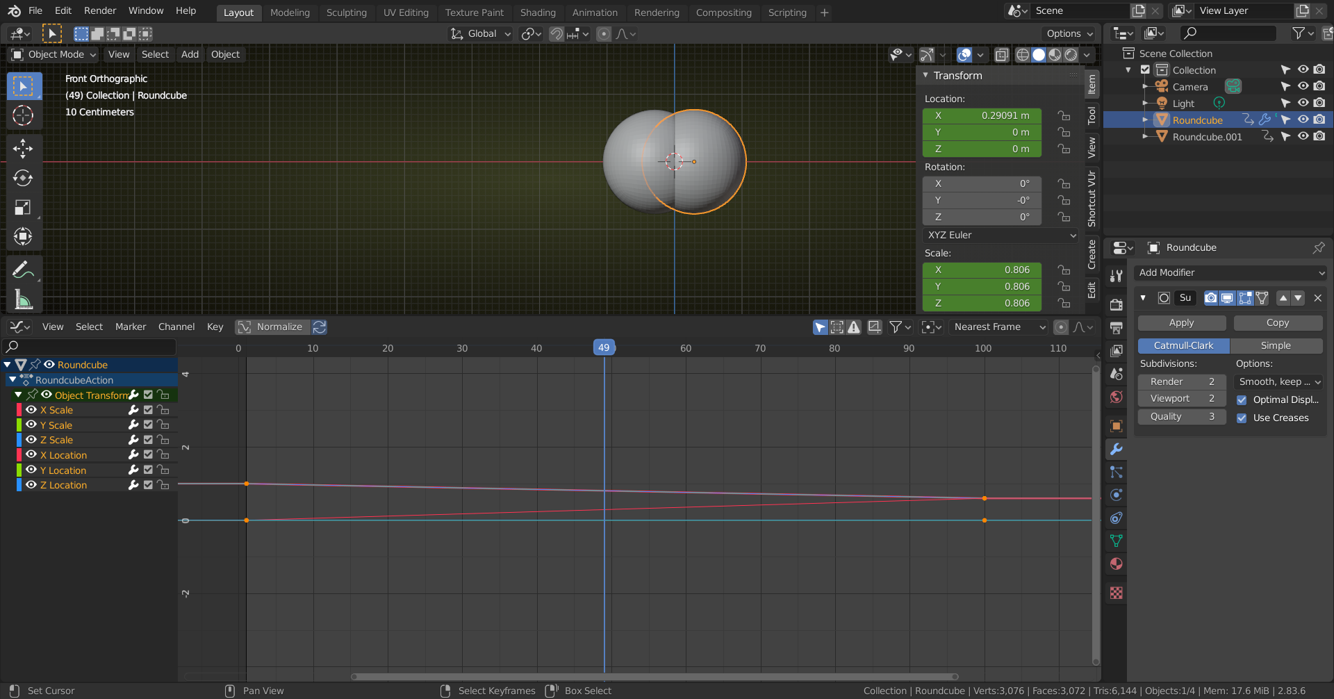
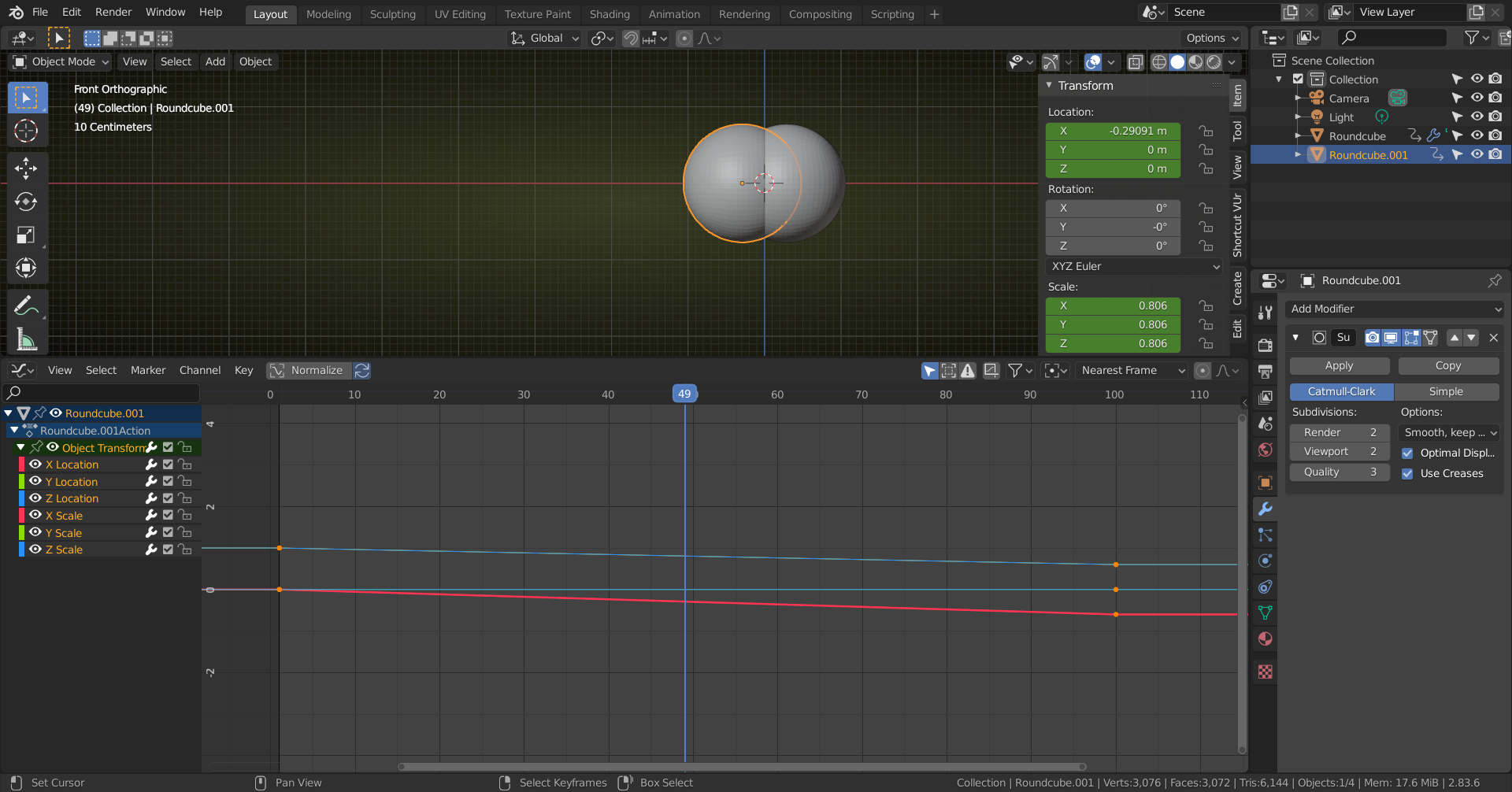
Now this is 2.83, but I can't imagine that 2.82 is different. Will try 2.82, just to make sure.
Apart from the fact that it seems rather 'clumsy/awkward' to keyframe Scale and Location separately, the order definitely should not make any difference!
Here's 2.82:
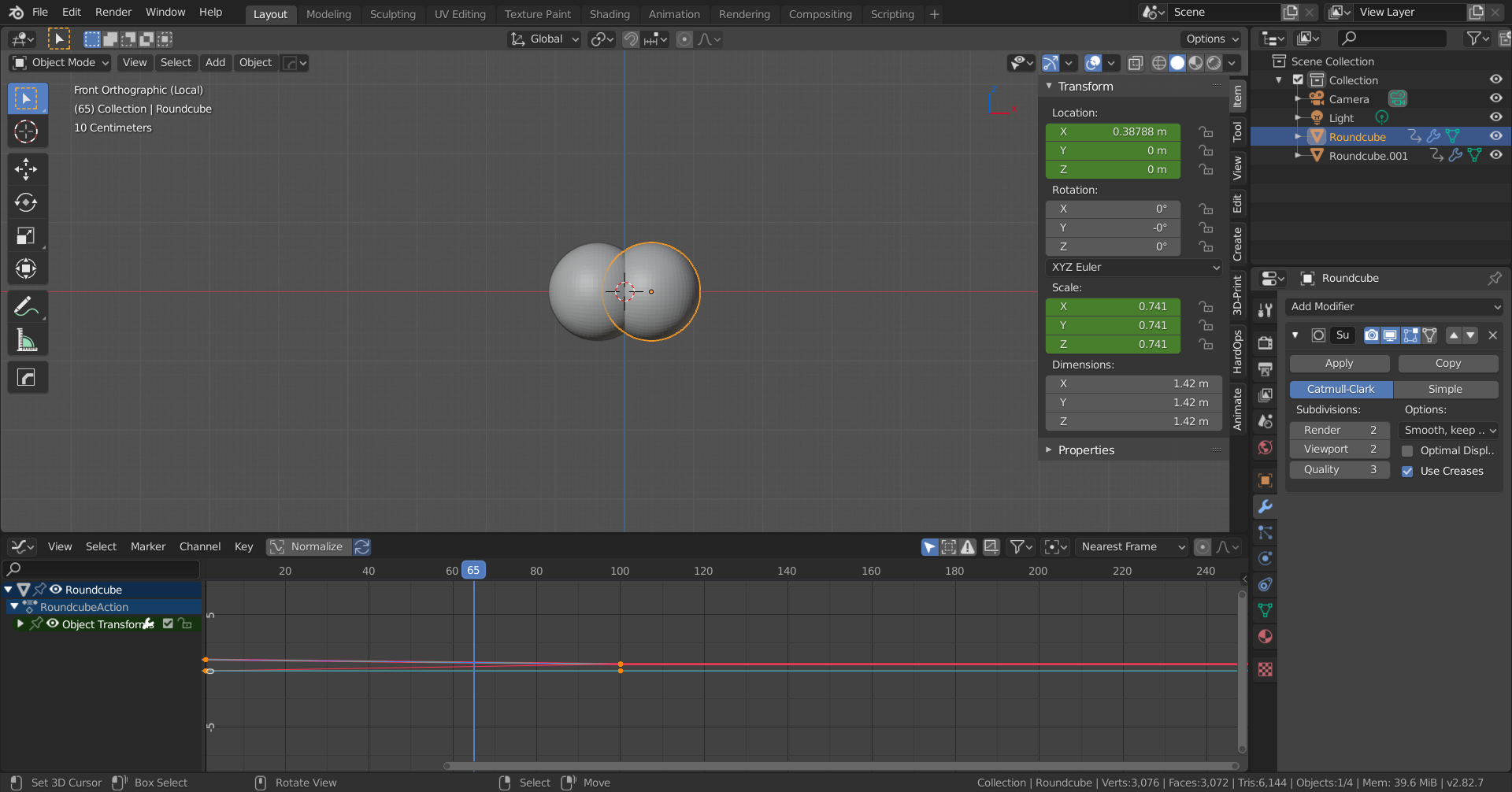
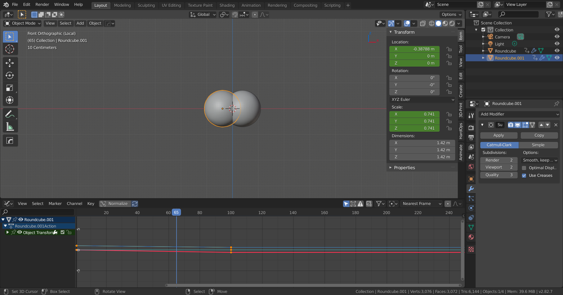
I didn't just save the file made in 2.83 and then opened it in 2.82, but set it up from the start (forgot to open the Object Transforms in the Graph Editor, but here also Scale and Location are switched between the two 'Cells').
I have no idea what is happening in your case. Please don't tell me it's the Camera Perspective ;)
OK I believe that I found the reason, but I have a new issue now. I repeated my experiment, but this time left the animations on standard bezier interpolation and didn't bother with SSM or shaders. Bingo! Order of keyframing made no difference. I have always had a problem with the graph editor in that I often get stuck with looking at lines that barely change over time as I could never work out how to change the scale on the axis, (on line help is always determined to direct you to scaling object rather than axis). Thankfully I found the 'view all' button and can now see what's happening, (or rather not). Because I was looking at a very narrow gradient before I hadn't realised that when I was switching to linear from bezier, this was not happening in some cases. Not sure why some ended up changing and some did. Double strange as I now cannot actually change the shape of any curve. It's obviously something I accidentally did in 2.79 as my 'Start file' was inherited from that when I moved to 2.80 etc. I know this as I can no longer change interpoloation mode via Key>Interpolation mode in Graph editor in 2.79, and I know for sure I used to be able to. This DOES work OK in a Blender file I obtained when I bought an add on, so it is my own stupid fault somewhere along the line. I thought it might be the 'F curve modifiers are disabled message' over the spanners in the graph editor. That was a red herring though as my imported Blender file had that 'problem' too, (just as well as there is nothing on the internet on how to enable F curve modifiers -- whatever that means). Can you help me re-enable my ability to change graph curve shape?
Are the interpolation modes greyed out like this?
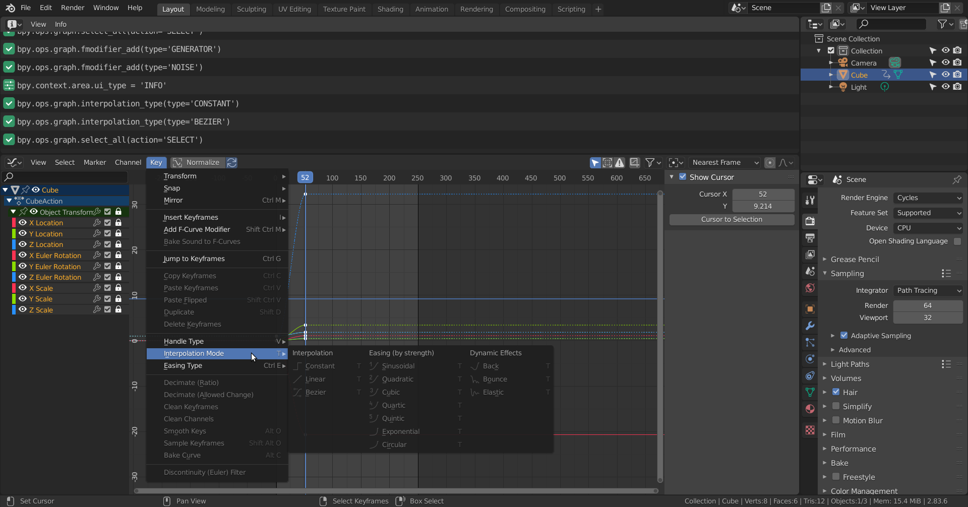
Then it could be that you 'locked' the channels (see lock icon at the right side of the channels). There is also the wrench icon that when not enabled will not use curve modifiers....
Also the interpolation only changes between selected keys, so you must have keys selected (not just the curve), but I guess you know that already...
I am just guessing here; don't know of any way to disable interpolation or modifiers 'permanently' through Preferences or so.
If this is not it, you should ask an expert like @waylow .
Thanks Spikeyxxx, you have solved everything. I just KNEW that somewhere along the line it was down to me being a numpty. I had no idea that you had to select the keys and not just the curve. I suspect that because I'm often only selecting one curve at a time I have keys selected by virtue of the last operation when I turn to the graph editor. That would explain why some curves went linear and not others. The other possibility is that when I clicked on a given parameter in the Graph Editor I accidentally changed the spanner from grey to white. Knowing me both mistakes were made! Mind you I'll forgive myself for not knowing about the spanners, as it's not exactly intuitive as to whether they are on or off and even what they do. The hover info just says 'F curve modifiers disabled' whether they are grey or white. What the heck is a F curve modifier anyway? Is that the interpolation control? Anyway, thanks for your help. At least I can change from Bezier to Linear now! Cheers!
What the heck is a F curve modifier anyway?
If you open up the N-Panel (right side) in the Graph Editor, you get a Tab called Modifiers (if you have them enabled via the 'wrench'):
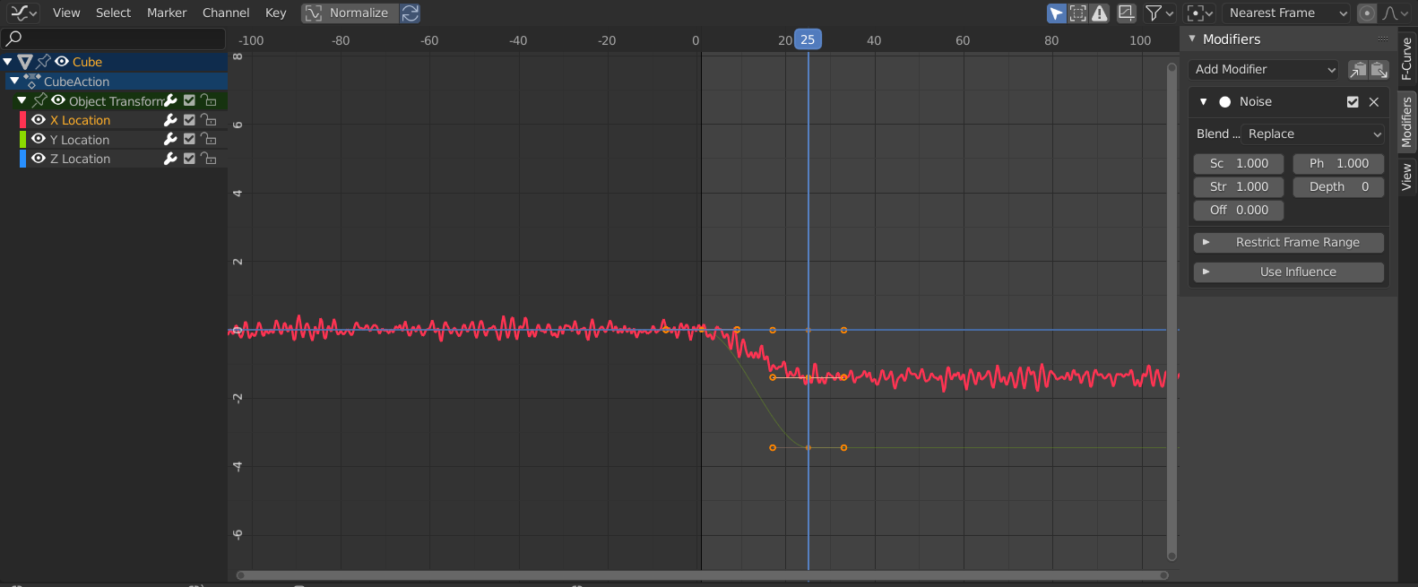
Here I added a Noise Modifier to the X Location and you can see what it does.
Sometimes used to fake a handheld camera shake, but there are many more Modifiers and they all modify the curve (or a part of it) n some way.
Hey Spikey, "Revive disabled f-curves" will try to reconnect any of the broken channels.
It doesn't do a lot for broken animation channels most of the time, as they are usually broken when the name of the channel cannot be matched to the name of the thing being animated (ie - the object, bone or property attached to any of those)
So you either have to rename the connection in each channel, or rename the control to match, revive, then rename the control back to what you want it to be called. (I haven't tested that, but just thought of this while typing)
It does actually fix broken driver channels in the case where the name of the object has changed, which breaks the drivers.
You can name it back to what it should be according to the curve, then "revive" and it will try to reconnect and fix them. You can't rename the object without editing each of the drivers though. (limitation in Blender)
Don't worry if none of that made sense, Jim. Hopefully it did to Spikey :)
Hi Jim, I'm not sure if you have taken the fundamentals of animation yet but I think it will really help you understand the graph editor and how animation data works. (well the basics anyway)
You did figure out that the order of the curves don't matter in the graph editor though.
One handy way to change the keyframe interpolation is in with the T key.
If you want to change the vector handle type, that is the V key.
If you haven't taken the course, then I highly recommend that you do. And if you get stuck or have any more questions, let me know. (But spikey will probably jump in and save the day first because he's a champion like that haha)